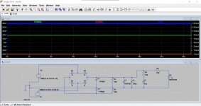
PerfectThis shows the voltage sources and the rails with ripple.
You can label points using the button shown. If you do that and run the simulation those points then appear in the traces and make it easier to follow.
Some characters are not allowed, it will tell you if you try and use them.
You can use the labels to electrically join points if they are miles away on a complicated circuit. So if you label two or more points with the same label they join electrically.
And that's it for today
does this work? im just sort of messing around with things at the moment trying to get used to it.
Attachments
Yes, it runs OK.
The LED current is high. If you left click R4 when the simulation has run you can plot the current (right hand scale). So 150 milliamps here.
Some things for you to experiment with.
1/ If you right click any of the labels on the graph (so for example v(n002)) you can change the colour which is useful if you want to make positive red, negative blue etc.
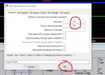
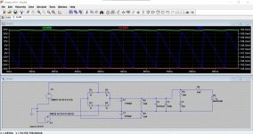
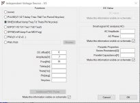
2/ If you want to see more detail of for example the ripple then set the start time of the sim some time after 0 as shown here. This will show detail from 9.9 seconds to 10 seconds. Now look at the LED current.
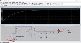
3/ Try changing the simulation to run from 0 to 0.2 seconds and look at the way the cap C5 charges up.
The LED current is high. If you left click R4 when the simulation has run you can plot the current (right hand scale). So 150 milliamps here.
Some things for you to experiment with.
1/ If you right click any of the labels on the graph (so for example v(n002)) you can change the colour which is useful if you want to make positive red, negative blue etc.
2/ If you want to see more detail of for example the ripple then set the start time of the sim some time after 0 as shown here. This will show detail from 9.9 seconds to 10 seconds. Now look at the LED current.
3/ Try changing the simulation to run from 0 to 0.2 seconds and look at the way the cap C5 charges up.
Attachments
Last edited:
Also you might find these useful.
1/ If you click 'Help' on the top line of LT there is a 'Help Topics'. Make sure you click 'Index'.
2/ If you go to the LT folder that should have been installed by default in your Documents Folder you will find a folder marked 'Examples'. Open that and look at the 'Educational' sub folder. There are countless worked simulation examples. Try the one called 'Audioamp'
I would recommend you save any with a different name BEFORE you alter anything on them such as parts values etc. That way you preserve the originals.
Attachments
 they are watching you...
 Remember the peak and rms thing and how to work them out. Look at the AC voltage and place the cursor over label on the graph. I labelled it VAC1 here. Press and hold CTRL and left click. You get the rms value from your 30 volt peak waveform.
If you miss with the cursor and accidently drag the trace instead (and you will
) then right click the graph and click 'Zoom to Fit'Attachments

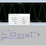
Remember the peak and rms thing and how to work them out. Look at the AC voltage and place the cursor over label on the graph. I labelled it VAC1 here. Press and hold CTRL and left click. You get the rms value from your 30 volt peak waveform.
If you miss with the cursor and accidently drag the trace instead (and you will
this any better?
Attachments
That is OK. R3 and C5 would not do much to the rail in a real build.
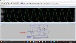
If you are wanting to simulate an amplifier then I would begin by using simple DC sources for the rails rather than trying to simulate the power supply as well. The PSU can be added later if you want to look at certain things like how well it rejects ripple and so on.
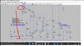
Try this one. It is a single rail amplifier that will just click and run (it will take a few seconds to complete the run).
You could then try and replace the single 56 volt supply with an AC voltage and bridge rectifier if wanted.
If you are wanting to simulate an amplifier then I would begin by using simple DC sources for the rails rather than trying to simulate the power supply as well. The PSU can be added later if you want to look at certain things like how well it rejects ripple and so on.
Try this one. It is a single rail amplifier that will just click and run (it will take a few seconds to complete the run).
You could then try and replace the single 56 volt supply with an AC voltage and bridge rectifier if wanted.
Attachments
Finaly for tonight as im going to watch the footie.
does this work, or have i got it totaly wrong?
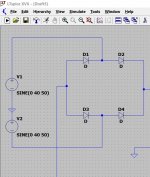
It is OK, however the voltage source V2 should have its connections swapped as the two AC voltages are in phase... so if it was a real transformer there would be 0 volts end to end.
It still all works though and would do for a real supply as well.
The 6.8p caps would be to small in practice to have any effect on the supply. 0.1uF perhaps in series with a 1 ohm would be a reasonable sort of set up. The 1 ohm defines a definite impedance and can be better than just adding a cap directly across a rail.
on the example amp in the educational folder what is the minor 700mv power supply? is this the input from a device?It is OK, however the voltage source V2 should have its connections swapped as the two AC voltages are in phase... so if it was a real transformer there would be 0 volts end to end.
It still all works though and would do for a real supply as well.
The 6.8p caps would be to small in practice to have any effect on the supply. 0.1uF perhaps in series with a 1 ohm would be a reasonable sort of set up. The 1 ohm defines a definite impedance and can be better than just adding a cap directly across a rail.
i get the +/- rails the other end.
is the frequency important?
also rather than write again,on that example amp you sent to me i cant get R5 and R6 to equate
the rail voltage is 56vdc yet its 54.35vdc to the base of Q4 and i only make it about 5mv drop across R5 (unless im doing something wrong)
does C3 have an influence?
also rather than write again,on that example amp you sent to me i cant get R5 and R6 to equate
the rail voltage is 56vdc yet its 54.35vdc to the base of Q4 and i only make it about 5mv drop across R5 (unless im doing something wrong)
does C3 have an influence?
The caps have no effect on the DC operating point in simulation. They are effectively ignored.
What are you doing or clicking to see 5 millivolts?
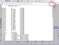
These are the DC voltages according to the sim. If you run the sim as posted you have to wait a few seconds for the run to complete. You can then close the graph and look at voltages.
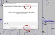
or...
you can set the 'Edit Simulation CMD' to do a DC only run. That brings up a window of all the voltages and currents at all the nodes. Close that window and you can probe the DC voltages and currents as normal.
What are you doing or clicking to see 5 millivolts?
These are the DC voltages according to the sim. If you run the sim as posted you have to wait a few seconds for the run to complete. You can then close the graph and look at voltages.
or...
you can set the 'Edit Simulation CMD' to do a DC only run. That brings up a window of all the voltages and currents at all the nodes. Close that window and you can probe the DC voltages and currents as normal.
Attachments
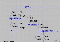
And calculating the old fashioned way...
R total equals 10k + 330k which is 340k.
I =V/R which is 56/340,000 giving 0.165 milliamps flowing in the series chain of the two resistors.
Voltage across the 10k is 0.165E-3 * 10,000 giving 1.65 volts.
Voltage across the 330k is 0.165E-3 * 330,000 giving 54.45 volts.
Total of the two equals 56 volts.
NOTE... the actual circuit also has Q4 drawing a tiny base current from the 10k resistor but in this case the value is microscopic and so can be ignored for a manual calculation. It doesn't really alter the practical result.
i was just using ohms law to see what the voltage drop was across that resistor, maybe i was doing it wrong
I'm already on it... I wondered
It is but I don't get what you get You hover over the resistor, do not click it.
Are you allowing the sim time to run? Look at the bottom left corner while it does so for the time elapsed. Even then you need to allow a couple more seconds for it to finalise.
You hover over the resistor, do not click it.Are you allowing the sim time to run? Look at the bottom left corner while it does so for the time elapsed. Even then you need to allow a couple more seconds for it to finalise.
Attachments
- Home
- Design & Build
- Software Tools
- Installing and using LTspice IV (now including LTXVII), From beginner to advanced