Because someone asked...
Here is a split rail supply.
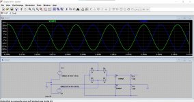
First image:
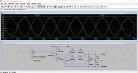
The voltages are all shown with respect to ground. This is the transformer with windings not connected. Notice how as one voltage on a winding increases, the other does so in the opposite polarity. The voltage between AC1 and AC2 is about 40 volts peak to peak. On a DVM that would read around 28.2 volts which is an rms value. 40/1.414 = 28.2v
Each winding is therefore 14.1 volts rms. So the transformer is a 14-0-14 volt ac type.
Second Image:
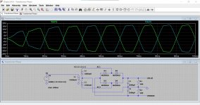
The transformer connects to a bridge rectifier and reservoir caps. The resistors are the load.
Notice how the AC voltage is clipped a little now. A real small transformer would behave like this because the diodes only conduct then the voltage on the winding exceeds the voltage on the cap. So they just top up the caps each half cycle.
Third Image:
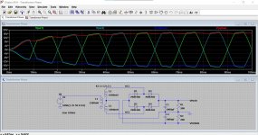
Shows all the voltages. Notice how the caps charge to the peak of the AC voltage.
If you place the cursor over a part and left click you will see the current flows.
The file attached will just click and run.
Here is a split rail supply.
First image:
The voltages are all shown with respect to ground. This is the transformer with windings not connected. Notice how as one voltage on a winding increases, the other does so in the opposite polarity. The voltage between AC1 and AC2 is about 40 volts peak to peak. On a DVM that would read around 28.2 volts which is an rms value. 40/1.414 = 28.2v
Each winding is therefore 14.1 volts rms. So the transformer is a 14-0-14 volt ac type.
Second Image:
The transformer connects to a bridge rectifier and reservoir caps. The resistors are the load.
Notice how the AC voltage is clipped a little now. A real small transformer would behave like this because the diodes only conduct then the voltage on the winding exceeds the voltage on the cap. So they just top up the caps each half cycle.
Third Image:
Shows all the voltages. Notice how the caps charge to the peak of the AC voltage.
If you place the cursor over a part and left click you will see the current flows.
The file attached will just click and run.
Attachments
yep i understand this, so if you remove the resistors there is not current flow
im trying the spice thing out but im having trouble with it in the sense that
1-i can only seem to be able to create a DC supply,not a/c
the rectifier bit i get(create your own)
2-when i add components i cant spin them so i am having to use them in a vertical aspect only, and the menu option for rotate is greyed out so it cant be used.
Spinning components is easy. Try this.
1/ Open a simulation of start with a new blank worksheet.
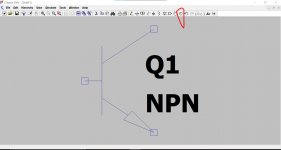
2/ Click the component symbol on the top line and then click NPN to place an NPN transistor on the page. Press OK
3/ Now left click the symbol on the page and it will attach.
4/ Now click the smaller of the two 'Hands' on the top line and go and place it over the transistor and left click it once.
You can now drag your transistor up to one of the rotate symbols on the top line. Click the symbol to rotate or use the other symbol to 'mirror'. When it looks how you want drag it back to the page and left click to drop it back in place.
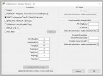
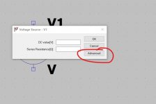
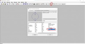
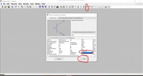
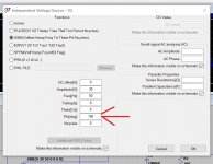
An AC supply is created using the Voltage symbol. Place it on the worksheet and right click it. Now select Advanced.
To create an AC supply that will generate say +30 volts DC when rectified we enter the following:
Offset = 0
Amplitude =30 (because that is the peak voltage. LT works in peak voltages here)
Frequency is 50Hz
The others we can enter zero for and lave the number of cycles blank. That means it runs continuously.
Click OK to save.
Add a ground symbol to the bottom of the voltage source.
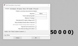
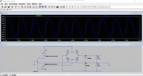
Now right click the blank workspace and select 'Edit Simulation'.
Enter 100ms as shown and click OK
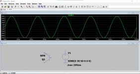
Now run the simulation and probe the voltage source and it should look like the last image.
1/ Open a simulation of start with a new blank worksheet.
2/ Click the component symbol on the top line and then click NPN to place an NPN transistor on the page. Press OK
3/ Now left click the symbol on the page and it will attach.
4/ Now click the smaller of the two 'Hands' on the top line and go and place it over the transistor and left click it once.
You can now drag your transistor up to one of the rotate symbols on the top line. Click the symbol to rotate or use the other symbol to 'mirror'. When it looks how you want drag it back to the page and left click to drop it back in place.
An AC supply is created using the Voltage symbol. Place it on the worksheet and right click it. Now select Advanced.
To create an AC supply that will generate say +30 volts DC when rectified we enter the following:
Offset = 0
Amplitude =30 (because that is the peak voltage. LT works in peak voltages here)
Frequency is 50Hz
The others we can enter zero for and lave the number of cycles blank. That means it runs continuously.
Click OK to save.
Add a ground symbol to the bottom of the voltage source.
Now right click the blank workspace and select 'Edit Simulation'.
Enter 100ms as shown and click OK
Now run the simulation and probe the voltage source and it should look like the last image.
Attachments
Here is a split rail supply.
First image:
The voltages are all shown with respect to ground. This is the transformer with windings not connected. Notice how as one voltage on a winding increases, the other does so in the opposite polarity. The voltage between AC1 and AC2 is about 40 volts peak to peak. On a DVM that would read around 28.2 volts which is an rms value. 40/1.414 = 28.2v
Each winding is therefore 14.1 volts rms. So the transformer is a 14-0-14 volt ac type.
Second Image:
The transformer connects to a bridge rectifier and reservoir caps. The resistors are the load.
Notice how the AC voltage is clipped a little now. A real small transformer would behave like this because the diodes only conduct then the voltage on the winding exceeds the voltage on the cap. So they just top up the caps each half cycle.
Third Image:
Shows all the voltages. Notice how the caps charge to the peak of the AC voltage.
If you place the cursor over a part and left click you will see the current flows.
The file attached will just click and run.
so do you have to put in the transformer as you have shown here or can you just draw it direct from the power source
so would this work as i have done it here? its my first attempt so it might not workHere is a split rail supply.
First image:
The voltages are all shown with respect to ground. This is the transformer with windings not connected. Notice how as one voltage on a winding increases, the other does so in the opposite polarity. The voltage between AC1 and AC2 is about 40 volts peak to peak. On a DVM that would read around 28.2 volts which is an rms value. 40/1.414 = 28.2v
Each winding is therefore 14.1 volts rms. So the transformer is a 14-0-14 volt ac type.
Second Image:
The transformer connects to a bridge rectifier and reservoir caps. The resistors are the load.
Notice how the AC voltage is clipped a little now. A real small transformer would behave like this because the diodes only conduct then the voltage on the winding exceeds the voltage on the cap. So they just top up the caps each half cycle.
Third Image:
Shows all the voltages. Notice how the caps charge to the peak of the AC voltage.
If you place the cursor over a part and left click you will see the current flows.
The file attached will just click and run.
Attachments
OK, so that's pretty good although there are a couple of things to do.
Try this.
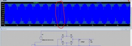
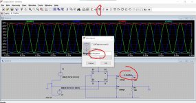
When you run it it all works OK but there is a little error with the voltage source set up. If you put your cursor on the black border next to the where it says V(n001) and you left click and hold then you can draw a small rectangle into the waveform to highlight just a small part.
So it should look like this. The two AC voltages are overlaid on each other and there lies the problem If you measured that on a meter then there is no voltage difference between the upper and lower voltage.
I'll show you what to do in a second.
Try this.
When you run it it all works OK but there is a little error with the voltage source set up. If you put your cursor on the black border next to the where it says V(n001) and you left click and hold then you can draw a small rectangle into the waveform to highlight just a small part.
So it should look like this. The two AC voltages are overlaid on each other and there lies the problem
If you measured that on a meter then there is no voltage difference between the upper and lower voltage.I'll show you what to do in a second.
Attachments
You have done something I would not have expected and there are two ways of 'fixing it.
Look at your lower voltage source V2. You have connected the - to ground which at first sight seems logical but this is AC remember and so what you have done is connected the voltage source so that it is in phase with the top one.
So two ways to fix. Do one or the the other.
1/ Snip the connections and reverse them.
2/ Right click V2 and add a phase shift of 180 degrees.
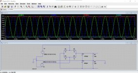
Now you should get this. Last image is how to highlight a smaller time period of the waveform. Draw a small rectangle anywhere on the waveform as shown.
Look at your lower voltage source V2. You have connected the - to ground which at first sight seems logical but this is AC remember and so what you have done is connected the voltage source so that it is in phase with the top one.
So two ways to fix. Do one or the the other.
1/ Snip the connections and reverse them.
2/ Right click V2 and add a phase shift of 180 degrees.
Now you should get this. Last image is how to highlight a smaller time period of the waveform. Draw a small rectangle anywhere on the waveform as shown.
Attachments
Perfect This shows the voltage sources and the rails with ripple.
You can label points using the button shown. If you do that and run the simulation those points then appear in the traces and make it easier to follow.
Some characters are not allowed, it will tell you if you try and use them.
You can use the labels to electrically join points if they are miles away on a complicated circuit. So if you label two or more points with the same label they join electrically.
And that's it for today
This shows the voltage sources and the rails with ripple.You can label points using the button shown. If you do that and run the simulation those points then appear in the traces and make it easier to follow.
Some characters are not allowed, it will tell you if you try and use them.
You can use the labels to electrically join points if they are miles away on a complicated circuit. So if you label two or more points with the same label they join electrically.
And that's it for today
Attachments

It doesn't matter to the simulation as far as getting the DC voltage goes but I am not sure if -90 is a valid statement mathematically. I've no idea on that.
90 degrees starts the voltage at the top of the sine, -90 starts it at the bottom but that can also be entered as 270.
90 degrees starts the voltage at the top of the sine, -90 starts it at the bottom but that can also be entered as 270.
Yes they both will work and both will give the same DC but they are different in themselves. If one is +90 and the other -90 then they are 180 degrees apart.
If you set up two voltage sources the difference is apparent.
A +90 sine starts 90 degrees into the cycle which is +28v above ground in your example.
A -90 sine starts as 90 degrees lagging from the initial start point and so begins at negative 28 volts.
What I don't know s whether that is valid mathematically, to say -90... I'm really not sure. You are specifying -90 as an angle on something that hasn't yet started. T= -5 milliseconds.
Dunno
- Home
- Design & Build
- Software Tools
- Installing and using LTspice IV (now including LTXVII), From beginner to advanced