You would measure output impedance in LTspice exactly the same method as you would use on the bench.
Add a current source (lets call it CS) between output and ground of say 20mA AC. Then plot the output voltage Vout. Then plot V(Vout)/I(Ics) and that is Zout. Ohms' Law ;-)
Jan
Add a current source (lets call it CS) between output and ground of say 20mA AC. Then plot the output voltage Vout. Then plot V(Vout)/I(Ics) and that is Zout. Ohms' Law ;-)
Jan
I just downloaded LTspice because poeple have been recommending it to me and this whole thing is extremely confusing. I have no idea how to import the parts into the program. Why cant it be any simpler..
Actually my only problem is how to get the tubes in it. Otherwise it seems like a straight forward program.
Would someone be kind enough to assist me with this?
Actually my only problem is how to get the tubes in it. Otherwise it seems like a straight forward program.
Would someone be kind enough to assist me with this?
This article was interesting:
LTSpice Simulation Using WAV Files
LTSpice Simulation Using WAV Files
<Snip> Learn how to interface with LTSpice using WAV files.
LTSpice has the capability to record data from voltage and current nodes as part of a transient simulation. Data is recorded in a WAV file. The data can be read back by voltage and current sources and used as inputs to other LTSpice circuits, viewed using a simple playback circuit or exchanged with common data analysis applications.
In this article, examples of general purpose recording and playback circuits and details of the data format are explored.
How to use .subckt MOSFET models in LTSpice
Getting this on the sticky for those that can use it
https://www.diyaudio.com/forums/sof...-subckt-spice-models-ltspice.html#post5817262
Getting this on the sticky for those that can use it
https://www.diyaudio.com/forums/sof...-subckt-spice-models-ltspice.html#post5817262
You can plot capacitance directly by following this:
Installing and using LTspice IV (now including LTXVII). From beginner to advanced.
Note that it's not capacitance unless the curve is flat. So you will see that the input impedance is only capacitive in a certain frequency range if your amp has an input resistor.
Installing and using LTspice IV (now including LTXVII). From beginner to advanced.
Note that it's not capacitance unless the curve is flat. So you will see that the input impedance is only capacitive in a certain frequency range if your amp has an input resistor.
Slightly OT but can't find a better fit:
Found this in another forum on LTspice, anybody can shine some liht on this:
Analog Devices--which now owns Linear Technology--has begun offering a simulation package called Isim-PE. Has anyone in this group used this program? Can you compare is with LTSpice-XVII?
Renesas bought an electronics company that had a version of Isim-PE that I've worked with. It has a limit of 50 analog nodes in a circuit. I was trying to simulate a circuit containming two fully-differential op-amps and other components, and it said I had too many nodes.
If you Google Isim-PE there's some info but not related to ADI.
Jan
Last edited:
")
Simulating tolerances in passive components
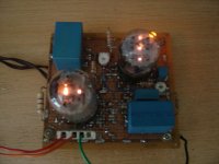
Hi Mooly and the guys here. I want to simulate a linear regulator with a 6FM7 and 6K11, properly working in real world. I would want to simulate it with some variations in the reference neon lamp (Ne4) automatically, like 75±5V and how it reflects in the performance of the device. How to do it if possible?
Hi Mooly and the guys here. I want to simulate a linear regulator with a 6FM7 and 6K11, properly working in real world. I would want to simulate it with some variations in the reference neon lamp (Ne4) automatically, like 75±5V and how it reflects in the performance of the device. How to do it if possible?
Attachments
I would want to simulate it with some variations in the reference neon lamp (Ne4) automatically
You might also look into Monte Carlo and Worst Case analysis.
I use the following 2SK389 model:
My devices however are 7.5 mA Idss. Is there any parameter I can change to get it into synch with my real device?
regards albert
This turns out to be 10.5 mA Idss..model 2sk389 NJF
+ Beta=51.76m Rs=8.008 Rd=8.008 Betatce=-.5 Lambda=11.22m
+ Vto=-.5275 Vtotc=-2.5m Cgd=18.28p M=.3367 Pb=.3905 Fc=.5
+ Cgs=20.07p Isr=112.8p Nr=2 Is=11.28p N=1 Xti=3 Alpha=10u Vk=100
+ Kf=92.85E-18 Af=1)
*SRC=2SK389;QSK389;JFETs N;Gen. Purpose;50V 10mA
My devices however are 7.5 mA Idss. Is there any parameter I can change to get it into synch with my real device?
regards albert
How to improve simulated vs measured filter frequency response?
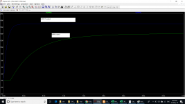
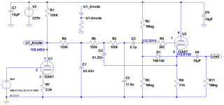
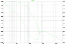
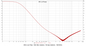
Hi, I'm changing the crossover points in a 4-way tube crossover that I didn't build. I'm having trouble getting the simulated and measured frequency responses to match. Specifically, the simulated crossover point (~-7dB for an 18dB slope) is 35Hz. The measured crossover point is 65Hz. I've attached the model of the bass filter, schematic, simulated frequency response and measured frequency response. Can anyone suggest how I might improve the match between the simulated and actual frequency responses please? I know the filter should be driven from a low impedance source but I didn't design it and I have to work with what I've been given.
Thanks!
Attachments
- Home
- Design & Build
- Software Tools
- Installing and using LTspice IV (now including LTXVII), From beginner to advanced