The current will want to run down the output winding rather than the VC without the bank of caps. Choose a 1/f frequency like 10 Hz or so to start, so that'd be about 2000 uF for an 8 ohm load. So that's opt, cap, then speaker. Feed the current source after the cap so it goes through the VC.
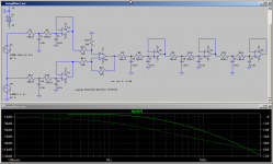
This is the filtering I was thinking of using for a subwoofer, but I have yet to build one for myself. I've had fine results using this method for test fixtures on mid drivers and tweeters. I hope the graphic is readable. 90dB down at 20Hz, so I think it'll do. You can remove stages if you find you don't need that much filtering to remove the audio from the test signal. It's differential inputs should be good to 50Vrms or so.
This is the filtering I was thinking of using for a subwoofer, but I have yet to build one for myself. I've had fine results using this method for test fixtures on mid drivers and tweeters. I hope the graphic is readable. 90dB down at 20Hz, so I think it'll do. You can remove stages if you find you don't need that much filtering to remove the audio from the test signal. It's differential inputs should be good to 50Vrms or so.
Attachments
I think for woofers I would use a current transformer. With some filter amplifiers you might even be able to come up with a universal impedance monitor this way.
Even more fun would be a true power meter. As P=I*V, just use a simple wide-band four quadrant multiplier and you're mainly done 'cept for the zero-cross issue (see below).
I haven't had much luck with winding my own current sensors. Bad response problems. I've heard that it might be possible to use hall effect sensors properly placed to achieve the same, but I've never tried. I still like sense resistors.
Impedance is a problem with music signals for a couple reasons. (1) Both voltage and current will cross zero, so there will be a dip where you get a divide by zero error when the current hits zero. You can even use a SPICE simulator with just a resistor to show this effect. (2) impedance is a frequency dependent quantity unlike resistance. It's only valid test input is a sine wave rather than an arbitrary signal such as music. If one was to use music as the input signal you have to do some FFT work to apply the matrices through the function f(z)=v/i and display the result with an RTA bar graph or something.
The result of that, I'd love to see
")
Average impedance may be calculated by dividing integrated v^2 by integrated i^2. Rectification may work instead of squaring.
I'm of the opinion average impedance is meaningless. If the result varies with input signal, it doesn't say much. Granted if the input signal contains immeasurable content at 30 Hz, you can't provide a result for that frequency.
To prevent divide overflow just ignore low values of v and i and/or compare v with i*max_allowed_impedance before dividing.
Well, that's in the digital domain. What if you wanted to do it analog only? Say you take the voltage and current signals of music playing through your speaker and divide them directly through an AD633, what's the signal result?
i dont know if i should start a new thread or not but ill try here one more time. i love davy's idea of the 100v thing but it turns out that the caps for this project are just crazy expensive (around 200$)
so is it possible to use a small NTC to measure the temp of the coil of a sub? what is a ntc? and what size would i need to buy i was told by the guy that sold me the coils that i could run these up to around 180 degrees celsius before having problems. so i would think being able to measure from 0-200 would be plenty of room.
does anyone have any suggestions?
- Status
- This old topic is closed. If you want to reopen this topic, contact a moderator using the "Report Post" button.