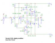
Just for fun, this is the Sinclair I simulated yesterday. 1969 was born. I made about 20 of these units in the seventies. Not so bad, but with typical early transistor circuit issues.
http://www.nvg.ntnu.no/sinclair/audio/z30.htm
It has celebrated its 40 years anniversary in November 2009. What a circuit!
http://www.nvg.ntnu.no/sinclair/audio/z30.htm
It has celebrated its 40 years anniversary in November 2009. What a circuit!
Attachments
Last edited:
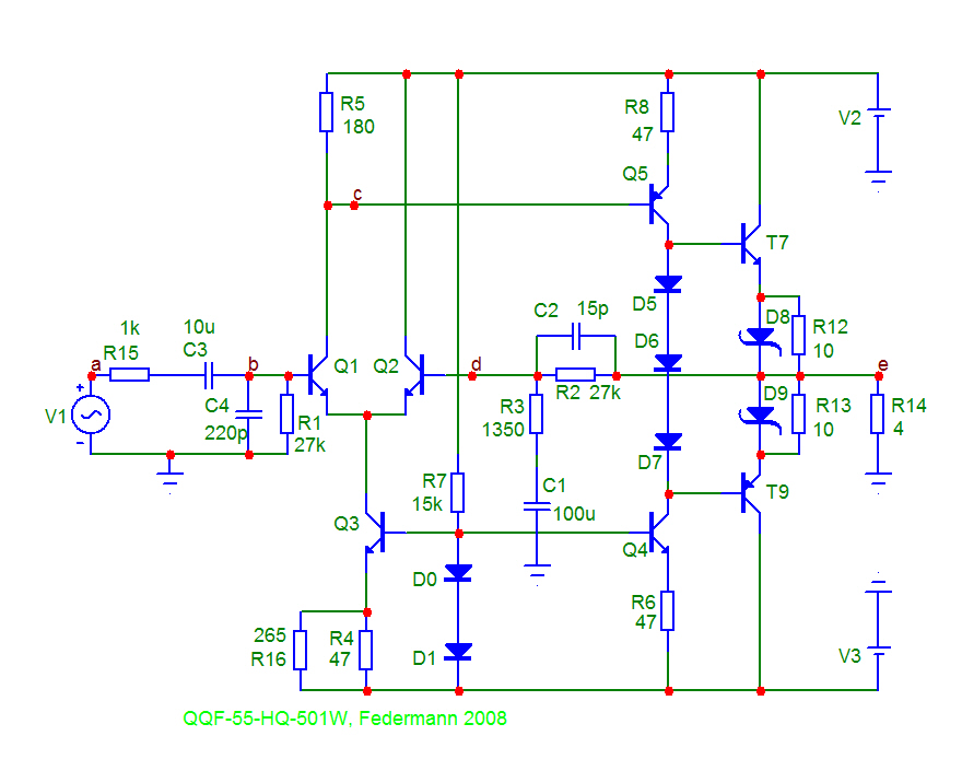
Try it with darlingtons, recomended by Federman....
I especially love his emitter 10R resistors and diodes (red circled)
Look - he was only 39 years late after Clive Sinclair!
And the D5,D6,D7 bias - wow!
Attachments
Last edited:
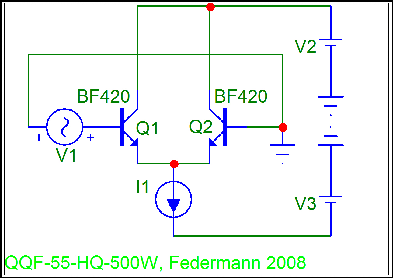
Just for fun, this is the Sinclair
Just for fun:
Increase the current of Q1 and Q2 to 4 +4 mA.
Move to the C3 and R6 set the best shape of the transmission characteristics, then put double the capacity of C3.
Q8 and Q9 just 10 mA.
Will have the best properties.
Good luck.
Federmann,
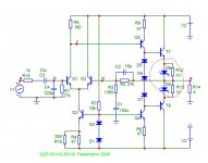
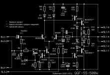
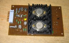
from you web page regarding QQF-55 KS 500W you say the following...
...which translates into...
...which is regarding for the so called power amp in the picture and schematic below (all from your web page) is able to source 500 Watts and even 1 kW?
Cheers Michael
from you web page regarding QQF-55 KS 500W you say the following...
Při napájení 2x35 V je typický maximální špičkový výkon na zátěži 4Ω 125 W. Pro 2x50 V pak 250 W, pro zájemce o větší výkon lze zapojit zesilovač do můstku a pak dosáhnout výkonu čtyřnásobného tj. 500W a 1kW!!! Jednotlivé hodnoty jsou patrny s předchozích grafů.
...which translates into...
When power is typically 2x35 V The maximum peak power at 125 W. 4Ω load for the 2x50 V at 250 W, for those interested in a higher power amplifier can be plugged into the bridge and then to achieve the feat fourfold ie 500W and 1kW! Individual values are evident in the previous graphs.
...which is regarding for the so called power amp in the picture and schematic below (all from your web page) is able to source 500 Watts and even 1 kW?
Cheers Michael
Attachments
Federmann,
from you web page regarding QQF-55 KS 500W
QQF-55 KS 500W is only a working title, as well as HQQF-55-502, HQQF-55-503W, etc.
Let's please with the original topic.
Last edited:
Pavel, please check this link
http://www.diyaudio.com/forums/soli...listening-characteristics-30.html#post2023360
http://www.diyaudio.com/forums/soli...listening-characteristics-30.html#post2023360
QQF-55 KS 500W is only a working title, as well as HQQF-55-502, HQQF-55-503W, etc.
Let's please with the original topic.
pro zájemce o větší výkon lze zapojit zesilovač do můstku a pak dosáhnout výkonu čtyřnásobného tj. 500W a 1kW!!!
edit: was too quick on the keyboard, Pavel has the accurate translation into English here
Last edited:
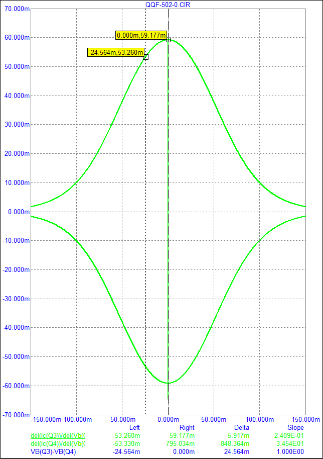
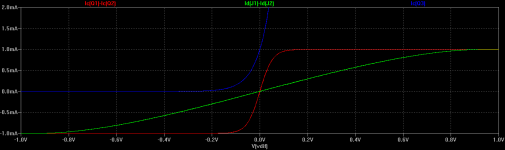
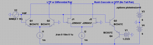
I wonder how this distortion (the existence of which is a divided issue) affects the Rush Cascode/NTP:
http://www.diyaudio.com/forums/solid-state/146346-cfp-gain-stage-modifications.html
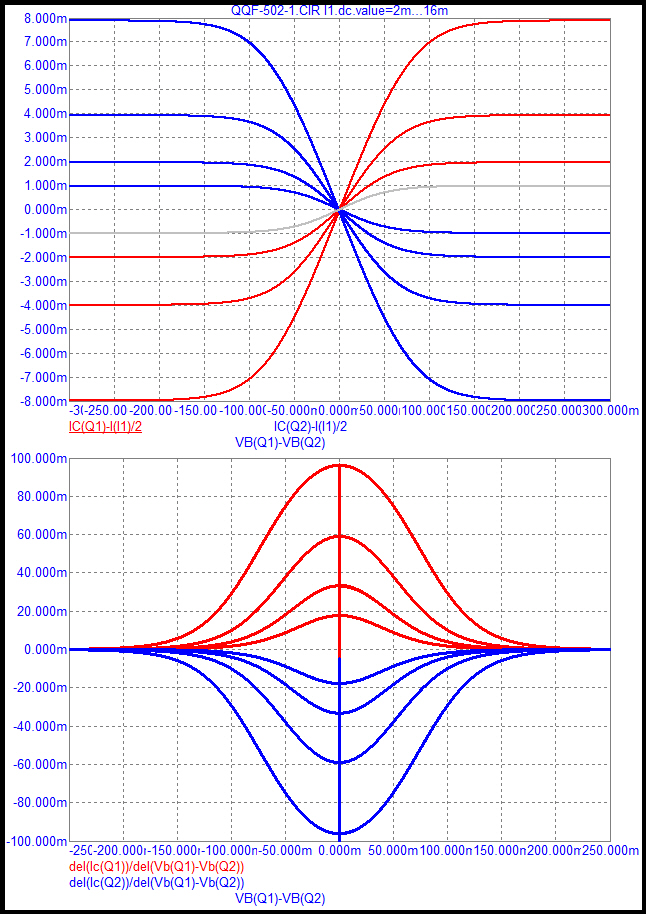
Transfer curves...
- keantoken
http://www.diyaudio.com/forums/solid-state/146346-cfp-gain-stage-modifications.html
Transfer curves...
- keantoken
Attachments
I wonder how this distortion (the existence of which is a divided issue) affects the Rush Cascode/NTP:
http://www.diyaudio.com/forums/solid-state/146346-cfp-gain-stage-modifications.html
Transfer curves...
- keantoken
Please make derivative curves, the result will be interesting.
Just for fun:
Increase the current of Q1 and Q2 to 4 +4 mA.
Move to the C3 and R6 set the best shape of the transmission characteristics, then put double the capacity of C3.
Q8 and Q9 just 10 mA.
Will have the best properties.
Good luck.
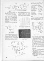
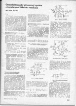
Federmann, I did that 25 years ago. I am sure you know my articles in 'Sdelovaci technika'.
Attachments
Last edited:
- Status
- This old topic is closed. If you want to reopen this topic, contact a moderator using the "Report Post" button.
- Home
- Amplifiers
- Solid State
- Influence of the delay amplifiers for listening characteristics