KLe said:Hi HKC
Just wondering how you are getting on ...
I think you can use a Multimetre.
I have used my Multimetre (DMM) to measure & match the Hfe of Transistors. So I am amusing that this can be done for Jfets also?
")
Hi KL
I just received the pcb from board factory today. I will post photos tomorrow.
I use multimeter to measure Hfe for NPN/PNP transistors as well. But JFets do not work this way. I had ordered 100 each of 2N5459/2N5462 from Mouser and I received these JFets last week so I am seeking some tool/instrument to get the JFets be matched.
Best Regards
HKC
Hi HKC,
look this PDF it's an excerpt from The New Frontier part1 from Borbely Audio web site. Match jfets by Idss and VP it's the best, if possible, otherwise by Idss only it's ok too. I think this is a very good way of matching the jfets and if you want to know more about this subject go to: http://www.borbelyaudio.com/special_articles.asp
Hoping you help. Maxpou
Attachments
maxpou said:Hi HKC,
look this PDF it's an excerpt from The New Frontier part1 from Borbely Audio web site. Match jfets by Idss and VP it's the best, if possible, otherwise by Idss only it's ok too. I think this is a very good way of matching the jfets and if you want to know more about this subject go to: http://www.borbelyaudio.com/special_articles.asp
Hoping you help. Maxpou
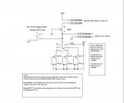
Hi Maxpou
Thank you for the pdf document. I also find this JFet Jig from web, what do you think about this:
Attachments
TriLithium said:They are almost the same except for the current sources. Both will work the same way.
Hi TriLithium
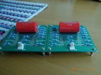
Thank you for your comment for the two JFet Jig circuits.
These are the two boards waiting to solder the matched 2N5459/2N5462 JFets:
Attachments
HKC,
Looking really good. Nice job on the boards.
I do not make multiple measurements on vgs at different values of id, but it certainly won't hurt, and you will likely have no offset with careful matching.
You can measure the idss with your digital meter, a 9 volt battery, and a 8 pin IC socket. You can wire one side of the socket for n channel devices and the other for p channel devices. You just short the gate to the source and measure the drain current with the jfet in series with the meter and battery. The idss of these devices is low enough that you don't need a limiting resistor, but watch the polarity. The other suggested circuits will work well too.
Good luck, and please keep us posted.
I think , the circuit showed by HKC is applicable to messure only npn device.
From my expirience all needed jfets should be matched in the same short period of time
for example diffferent room temp. ( 20 or 25 C deg.) will cause difference of the Idss parameter even +/- 0,1mA
From my expirience all needed jfets should be matched in the same short period of time
for example diffferent room temp. ( 20 or 25 C deg.) will cause difference of the Idss parameter even +/- 0,1mA
KLe said:HKC
Looking good ... nice
You wouldn't have happened to get more than 2 PCBs made ...
Hi KLe
Yes I use to make 10 boards for each design as this is the minimum order quantity to make pcb in our country.
jonusgrumby said:HKC,
Looking really good. Nice job on the boards.
I do not make multiple measurements on vgs at different values of id, but it certainly won't hurt, and you will likely have no offset with careful matching.
You can measure the idss with your digital meter, a 9 volt battery, and a 8 pin IC socket. You can wire one side of the socket for n channel devices and the other for p channel devices. You just short the gate to the source and measure the drain current with the jfet in series with the meter and battery. The idss of these devices is low enough that you don't need a limiting resistor, but watch the polarity. The other suggested circuits will work well too.
Good luck, and please keep us posted.
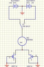
Hi Tom
Thank you for giving advice for idss measurement method. Please see and confirm the attached drawing is correct:
Attachments
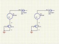
AndrewT said:re post 72:
turn the battery symbol back to front for the negative supply (Pchannel).
Instead of an ammeter (amps setting on a meter) use a resistor and measure the voltage drop.
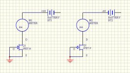
Hi Andrew
Thank you for correcting me. I attached a revised schematic.
It is a good option to use a resistor to replace the ammeter in this issue. What is the resistor value and the voltage drop? Is there any formula to calculate the resistor value and the voltage drop?
Thanks again
Attachments
Hi,
since most of the time you are measuring a few mA then using 1k0 as the current monitoring resistor allows 1V equivalent to 1mA.
1.86V equivalent to 1.86mA, +-tolerances on resistor +-tolerances on meter when on 2000mVdc scale.
But, if the voltage drop across the resistor becomes significant compared to the supply voltage then the device under test (DUT) becomes subject to a varying test voltage. With only 9V available you would be better off using a 100r resistor for all currents under 10mA and 10r resistor for currents above 10mA.
using,
1k0 ....1V.. eqiv 1mA
100r...1V ...eqiv 10mA
10r 100mV eqiv 10mA.
AndrewT said:Hi,
since most of the time you are measuring a few mA then using 1k0 as the current monitoring resistor allows 1V equivalent to 1mA.
1.86V equivalent to 1.86mA, +-tolerances on resistor +-tolerances on meter when on 2000mVdc scale.
But, if the voltage drop across the resistor becomes significant compared to the supply voltage then the device under test (DUT) becomes subject to a varying test voltage. With only 9V available you would be better off using a 100r resistor for all currents under 10mA and 10r resistor for currents above 10mA.
using,
1k0 ....1V.. eqiv 1mA
100r...1V ...eqiv 10mA
10r 100mV eqiv 10mA.
Hi Andrew
The information you sent is very detail and useful. Since I am not an expert person I feel the one with ammeter seems easier to me. What is the benefit to use resistor instead of ammeter in a JFet jig circuit?
Best Regards
PS: I revised the jig schematic as follow:
Attachments
- Status
- This old topic is closed. If you want to reopen this topic, contact a moderator using the "Report Post" button.
- Home
- Amplifiers
- Solid State
- Inexpensive JFET Preamp