Hi,
I'm so glad you are!
I guess this is the moment when you succeeded. You now know that the project was a good decision and works great. This is very good to hear (no turn-on/off noise, no offset, no hum, good sound). Not even the slightest functional problem, as it seems!
I'm happy for you too, even though I couldn't contribute.
Can you show your test setup?
Sebastian.
I'm happy this Friday!
I'm so glad you are!
I guess this is the moment when you succeeded. You now know that the project was a good decision and works great. This is very good to hear (no turn-on/off noise, no offset, no hum, good sound). Not even the slightest functional problem, as it seems!
I'm happy for you too, even though I couldn't contribute.
Can you show your test setup?
Sebastian.
That speaks for you and your experience ")
No, I meant photos of your test setup with the board, heat sink, trafo, etc.
Sebastian.
That's it.
No, I meant photos of your test setup with the board, heat sink, trafo, etc.
Sebastian.
Makes me wonder. It should actually stay below hand warm. How hot does the chip get (to the touch, or better in degree) at what power (did you measure the power)?
With 112x75x68mm, the actual dimensions are not that big. At such sizes, the thickness of the sink plate matters much. And the deep fins probably need a steady convection to deliver the 1K/W ratio...
And pictures?

I'm still happy it works great. I had some doubts wether I would like it after we disagreed about the beta test (and I couldn't participate), but that's over now that it's a success!
With 112x75x68mm, the actual dimensions are not that big. At such sizes, the thickness of the sink plate matters much. And the deep fins probably need a steady convection to deliver the 1K/W ratio...
And pictures?
I'm still happy it works great. I had some doubts wether I would like it after we disagreed about the beta test (and I couldn't participate), but that's over now that it's a success!
To be honest I played rather loud so it's natural with heat.
You could actually _save_ money if you did build the first amp now but I respect your standpoint. No hard feelings from my side.
It looks good at the moment so I really hope that many of you also build the amp. It's rather common, so it seems, that many DIY'ers buy pcb's, parts etc but never get their projects finished. It's OK if all of you order 100 pcb's and noone build but I would think it had been more fun if as many as possible can get music out of their amps.
Hi P-A
If it sounds as good as you say, it will be worthy of all the waiting.
It's three weeks now and those darn parts still haven't arrived.

In my case the chip will be attached to an SK42 heatsink. Hope this will be sufficient now that you have mentioned the large heat development of the amp.
Happy listening
Walter
If it sounds as good as you say, it will be worthy of all the waiting.
It's three weeks now and those darn parts still haven't arrived.
In my case the chip will be attached to an SK42 heatsink. Hope this will be sufficient now that you have mentioned the large heat development of the amp.
Happy listening
Walter
Hi P-A
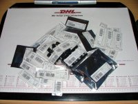
Guess what...., the parts finally arrived today.
Having to wait so long wasn't punishment enough!!
I was charged with a 143 Euro bill to cover VAT and customs fee!?
The package was only 129 Euro. Think I'm gonna make a few phonecalls tommorow to the customs office.
This is sofar the most expensive GC I've built. Anyway, I can finally start on the darn thing. Hope I don't get to stressy with soldering all that SMD stuff.
Keep you posted.
Cheers
Walter
Hi P-A
Aren't we a bit optimistic? Target is more in the near of "this weekend".
I already placed a few parts on the board to check how it looks and I must say it's not an impossible task to solder that SMD stuff. All this will be done with a magnifying glass ofcourse.
Cheers
Walter
Aren't we a bit optimistic? Target is more in the near of "this weekend".
I already placed a few parts on the board to check how it looks and I must say it's not an impossible task to solder that SMD stuff. All this will be done with a magnifying glass ofcourse.
Cheers
Walter

Solder all SMD parts except for the opamp. Check the voltage with an external power supply if you have the opportunity. If not, solder the rectifier bridges also. Then check that the voltages are 11-13 volts. After that solder all other parts excpet for the LM3886. Check the opamp and that you have signal from it. The gain should be slightly higher than 1. Check also the offset voltage which shall be less than 100 uV (or what the datasheet for the opamp says).
After that, finally, solder the LM3886 or mount it first on the heatsink then solder. This depends how your case and heatsink looks like.
.... and then put in the fuses if you haven't done this already. Start with 1 A slow just as a precaution. Apply voltage, either from the mains directly or via a variable transformer.
Then you will have a working amp.
Hi P-A
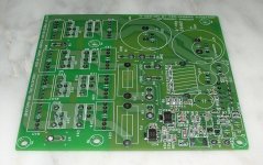
This is were I am so far (see picture). I'm still missing C1, C6, C7 and C14 --- C21. Ordered those from Elfa and they should have arrived yesterday, but they didn't. I'm going to proceed now with the "magnificent custom made P-A coil", diodes, fuseholders and the electrolytic cap's C4, C10 and C12.
Cheers
Walter
Attachments
Looks good! A proof of that it isn't so hard after all to solder this.GeWa said:Hi P-A
This is were I am so far (see picture). I'm still missing C1, C6, C7 and C14 --- C21. Ordered those from Elfa and they should have arrived yesterday, but they didn't. I'm going to proceed now with the "magnificent custom made P-A coil", diodes, fuseholders and the electrolytic cap's C4, C10 and C12.
Cheers
Walter

You are not too late because we haven't started yet. When Walter and/or Anders has built their amps and feel that they have succeeded I will start collecting money for the big order. Walter, Anders, when are you ready?Roushon said:If I am not too late tell me the procedure to get the kits...


- Status
- This old topic is closed. If you want to reopen this topic, contact a moderator using the "Report Post" button.
- Home
- Group Buys
- Industrial SMD Gainclone - group buy