Perhaps toggling through "Le" (normal, lossy le, semi inductance le) by double clicking them, and maybe semi inductance Le could be green. Then if semi inductance model is chosen (green Le), a new small window could pop up asking for the 3 extra parameters. If you needed to change these parameters you would cycle through until Le is green again and the box would pop up again.
Hi just a guy,
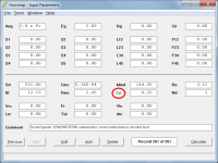
Great minds think alike - I too had decided to use a green Le label to indicate when the semi-inductance model option is being used (see Attachment 1). The red Le label will be retained for the Lossy Le option, and the Lossy Le functionality will remain unchanged.
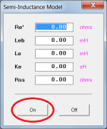
The semi-inductance model pop-up input parameters window will be as shown in Attachment 2, and will be opened by double-clicking on the Le text box, rather than by toggling the Le label. If the Lossy Le option is currently selected, it will be automatically replaced by the semi-inductance model option when the 'On' button is clicked to activate the semi-inductance model.
I trust that this functionality will be okay
") .
.Kind regards,
David
Attachments
Last edited:
Wow!
For those of us with smaller mental capacity, where/how do we find these values?
More accurate simulations are highly valued.
Thanks to all involved!
Almost no manufacturer provides them on the spec sheet so for now you'll have to measure them yourself or find specs that were measured by someone else (but usually people only post the common t/s unless they post a screenshot of the measurement results).
I'm hoping that once people are aware of the issue and aware that something can be done about it that they will start posting these specs as well. I'm sure Ricci will be in, so stuff he measures at data-bass might have these specs included.
Anthony one day we should sit down with a beer and discuss motor design. I was out your way last week visiting clients.
Sounds good, although you must know this is not my area of expertise. I only started looking into motors as an offshoot of my lossy le study.
Hi just a guy,
Great minds think alike - I too had decided to use a green Le label to indicate when the semi-inductance model option is being used (see Attachment 1). The red Le label will be retained for the Lossy Le option, and the Lossy Le functionality will remain unchanged.
The semi-inductance model pop-up input parameters window will be as shown in Attachment 2, and will be opened by double-clicking on the Le text box, rather than by toggling the Le label. If the Lossy Le option is currently selected, it will be automatically replaced by the semi-inductance model option when the 'On' button is clicked to activate the semi-inductance model.
I trust that this functionality will be okay
Kind regards,
David
Looks great.
In light of the recent events it seems I can improve the lossy le tool, although I don't know if it would be worth the bother as I'm not sure Hornresp could simulate it.
Bolserst showed that this can be accurately simulated as a variable low pass, so it should probably looked at from that perspective if possible.
The normalized Le info I have will show how much the low pass filter affects things for different drivers.
The problem is that I'm not sure Hornresp could do these calcs, since it appears that the low pass slope would have to be calculated and implemented at every frequency. Every frequency would need a different low pass slope.
Anyway, the existing tool works well enough and I'm not excited about another huge research project right at the moment but it's something I've been thinking about.
Sounds good, although you must know this is not my area of expertise. I only started looking into motors as an offshoot of my lossy le study.
Well I can agree with you on this one. But you are full of ideas. That's the beginning of learning anything. In fact it's how I started.
Wow!
For those of us with smaller mental capacity, where/how do we find these values?
More accurate simulations are highly valued.
Thanks to all involved!
It all starts with people being able to use the information. Then people asking for the information. Similar to the 80's when Thiele/Small were getting more widely known. It took a little while.
Now we can email our distributors and ask for the information pretty easily at no cost to ourselves.
Hi just a guy,
Great minds think alike - I too had decided to use a green Le label to indicate when the semi-inductance model option is being used (see Attachment 1). The red Le label will be retained for the Lossy Le option, and the Lossy Le functionality will remain unchanged.
The semi-inductance model pop-up input parameters window will be as shown in Attachment 2, and will be opened by double-clicking on the Le text box, rather than by toggling the Le label. If the Lossy Le option is currently selected, it will be automatically replaced by the semi-inductance model option when the 'On' button is clicked to activate the semi-inductance model.
I trust that this functionality will be okay
Kind regards,
David
I likes it! I likes it alot.
Inching ever so slowly into a lean mean simulation machine!
Thanks.
I was thinking more along the lines of which low cost measurement tools/methods/variations/applications can provide these values. What is needed to get going on the hobbyist workbench?
I am very aware they are not specified in from most manufacturers, I think the fastest way is to just start measuring and post the specs on the drivers measured. Waiting for industries to implement new methods or standards can take forever. Luckily we live in a world where we do not have to wait for an industrial mindset lagging behind.
Last edited:
Room Eq Wizard and ARTA give these extra parameters as I understand it, you don't have to do anything different, just measure the driver as usual and note these extra parameters. Then use them in Hornresp after the next update. As for hardware to run REW and ARTA, it's a simple jig you can diy with $2 in parts that you probably already have, just a couple of 3.5 mm jack ends and a resistor. Doesn't have to be a high power resistor, doesn't have to be any specific value as long as you know what it is (although some values are better for some applications).
I'm not sure whether WT2, WT3, DATS give these parameters, never had any of that hardware. I think the S&L WT2 might, it's the best of the bunch of this type of hardware/software combo.
I'm not sure whether WT2, WT3, DATS give these parameters, never had any of that hardware. I think the S&L WT2 might, it's the best of the bunch of this type of hardware/software combo.
Last edited:
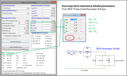
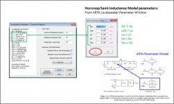
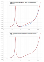
The documentation for REW and ARTA(LIMP module) both reference the Thorborg et al AES papers as the source for the impedance model, but it is implemented slightly differently. Hopefully the attached pics will help identify where to grab the required semi-inductance parameters for use in Hornresp.
If you have text files of impedance measurements taken with other programs, REW can import them to perform the calculations. Oh, speaking of REW, I noticed recently that the curve fitting on the impedance was not so good for some woofers. I mentioned this to the author of REW (JohnPM on diyAudio) and he will be releasing a fix in the next Beta version.
I use an Excel spreadsheet to perform a least squares fit for these parameters if a manufacturer provides traditional TSP and data for the free air impedance curve. It also allows manual tweaking if needed. If only a plot of the impedance curve is available, it is also possible to extra the data to perform the fit using tools like WebPlotDigitizer - Extract data from plots, images, and maps
I have data for a few of the Dayton subwoofers I can post later this week for people to “play” with once the Hornresp update has been released. If there are any woofers from the Databass website that are of particular interest, let me know and I will see if I can get the numbers included in the post. Ricci usually provides a free air impedance curve for each driver along with the traditional TSP.
Attachments

... If you have text files of impedance measurements taken with other programs, REW can import them to perform the calculations. Oh, speaking of REW, I noticed recently that the curve fitting on the impedance was not so good for some woofers. I mentioned this to the author of REW (JohnPM on diyAudio) and he will be releasing a fix in the next Beta version....
Is this what you meant:
http://www.avsforum.com/forum/155-d...lilmikea-s-diy-impedance-measurement-jig.html
About midway down the page:
"Clearly - there is a bit of a difference below 30 Hz, the deviation gets pretty significant by 10 Hz. Admittedly - the REW sweep takes 10 seconds or less, the WT2 sweep takes a minute or so. While a similar approach, the WT2 uses a more accurate method of calculating impedance, and in this comparison, the WT2 yields much better data below 30 Hz."
Much of that thread is commenting on the quality of the measurements using a sound card. And comparing them to the WT2.
My two cents is buy the WT2. It's a quality piece of instrumentation and can measure very accurately and repeatedly.
I use the woofer tester pro. It's not cheap but again it is accurate. And matches a Klippel analyzer in a heart beat for making the same measurements on the same driver. It's also a little cheaper than a Klippel analyser.
Is the change described in REW Beta Release - Changes in REW V5.19 beta 9 | AV NIRVANA ?Oh, speaking of REW, I noticed recently that the curve fitting on the impedance was not so good for some woofers. I mentioned this to the author of REW (JohnPM on diyAudio) and he will be releasing a fix in the next Beta version.
.
No, I was talking about the matching of model to measurements, not the measurements themselves. The issue you linked to is with mismatch in the LF response of the two channels in the soundcard. Both REW and ARTA can compensate for it, but it is up to the user to realize his particular soundcard has an issue and perform the extra calibration steps. Also, it is best to perform impedance measurements with an amplifier between soundcard and woofer so you can use a low value series resistance.
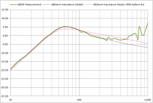
Attached is an example of the semi-inductance model matching I was talking about.
Results are shown before and after the fix. (JohnPM had sent me a pre-release to try out)
Looks like it isIs the change described in REW Beta Release - Changes in REW V5.19 beta 9 | AV NIRVANA ?
“…There have been some improvements to the Thiele-Small parameter optimization to improve fitting to the impedance measurement…”
Attachments
@ mwmkravchenko
Yeah new comps can be a pain, but worth it in the end
@ bolserst
It only seems to make a difference above about 100Hz. Which shouldn't be an issue with subs !
Yeah new comps can be a pain, but worth it in the end
@ bolserst
Attached is an example of the semi-inductance model matching I was talking about.
It only seems to make a difference above about 100Hz. Which shouldn't be an issue with subs !
Surprisingly, getting the semi-inductance parameter value incorrect by poor matching above 100Hz does affects the response below 100Hz as it shifts the ratio of resistance to inductance even though the total impedance may be quite close. In this case, it failed to full capture the Q'ing up of the response...still not too shabby compared to the traditional model.
This is one of the unique things I found with the semi-inductance model. Since it is modeling the physical reality of the lossy iron core, getting a match above 100Hz provides proper behavior below 100Hz. In comparison, I noticed least-square fitting of the more generic L2R model, or Wright model did not always match response measurements at low frequencies even though impedance match at high frequencies was reasonably good.
This is one of the unique things I found with the semi-inductance model. Since it is modeling the physical reality of the lossy iron core, getting a match above 100Hz provides proper behavior below 100Hz. In comparison, I noticed least-square fitting of the more generic L2R model, or Wright model did not always match response measurements at low frequencies even though impedance match at high frequencies was reasonably good.
Attachments
Last edited:
- Status
- This old topic is closed. If you want to reopen this topic, contact a moderator using the "Report Post" button.
- Home
- Loudspeakers
- Subwoofers
- Inductance Cancellation Techniques