HowdyGood to see you back on diyAudio.
The comment concerning REW and ARTA was supposed to be aimed at the manufactures, not the end user. Both software packages are currently used by many manufacturers, so it would be easy for them to start including the extended inductance model parameters. Back in the 80s it was tough to get even the basic TSP from most manufacturers, but slowly that changed. With one manufacturer already including the semi-inductance parameters in their datasheets…hopefully more will follow.
Ok, I understand now and that's my wish too. But again, the smaller manufacturers are t;he ones dabbling in ultra long stroke drivers and they generally don't want inductance information in the hands of their customers. Fi, manufacturer of one of the drivers in my study that was affected by this issue worse than any I have seen, does not even have an Le spec in their specsheet. Not anywhere on the website. Customers that email to ask about Le are flat out ignored. And like many other long stroke manufacturers, they are likely basing their xmax spec on a simulated Bl curve alone, ignoring Le (and Cms) completely. SI frequently quotes qtc based on a simple (probably WinISD) sim as if the measured qtc will be anywhere close to the simulated qtc.
It would be fantastic if the larger companies were more forthcoming about inductance and maybe one day they will be, but the real problem is with the ultra long stroke manufacturers and getting any type of relevant information from them is going to be a problem.
And I suppose the biggest problem is the customer. Most people are not aware of this issue at all. Even the few that have noticed that sims sometimes don't match measurements aren't aware of the reason. In my experience, most people that are made aware of the issue don't care - they simply continue to ignore lossy Le and use WinISD as if it were even close to accurate. It's not likely the supply side will change without demand from the demand side.
Unibox does contain an additional [R||L] term, but unfortunately does not include the semi-inductance parameter needed to properly model the LF behavior. BTW, Unibox also models 4th order bandpass enclosures, although now that I think about it the port “transmission line” model is in error similar to WinISD.
Discrepancy between WinISD & HornResponse (#12, #15)
...
In case you weren't aware, simply increasing BL will not overcome the effect of the semi-inductance on the response. The shape of the response is mainly coming from the electrical filter effect of the inductance on current thru the voice coil, not from the motor being severely underdamped. Bumping up magnet strength by 40% in an attempt to compensate for what looks like an underdamped woofer will not have the desired effect. If the blocked impedance remains the same the response shape will stay roughly the same, but appearing to shift to the right. Basically you will gain output above resonance by the expected amount(~3dB), but lose output below resonance because of overdamping. (see attached example)
Great information, thanks.
My comment about derated motor strength was based on the method I used to create the lossy Le method. As you know, all it does is derate Bl, and IIRC the amount Bl had to be derated to match the measurement was in the ballpark of 20 to almost 40 percent in the drivers I studied. So based on this (the shape of the measured vs simulated frequency response - basically a qtc comparison), it appears as though the driver has lost 20 - 40 percent motor strength compared to what the simple t/s (a simple sim) would suggest.
Last edited:
Hello Steve, and hello Anthony!
I'm sad to say that in terms of two simple points the driver industry on the large scale has fallen into the doldrums.
The vast majority of drivers are simple ring magnet two piece T-yoke and a washer that acts as a top plate to "focus" the potential magnetic flux.
They are dirt cheap to make. The two piece T-Yoke requires a serious relaxation in the voice coil former to pole piece clearance tolerances. This wastes potential motor energy. Yes loudspeakers are motors. Linear motors.
Second point. Means and methods to make a low inductance long throw woofer are well studied, well understood and fairly easily available.
I appreciate the prompting to include the complex inductance figures. The Thorburg model is a good beginning. It is not an orphan out there in the research world. It is a well thought out model that has at least been taken up by one manufacturer. And it's good to see.
Creating a low inductance long excursion motor can be done. One example cited by bolserts is the DD drive by JBL. It uses two coils and two motors that are spaced apart in such a manner that when the first coil is nearing it's limits of potential push or pull, the second motor coil combination is just coming into it's happy space. It takes over and keeps on pushing and or pulling. Think tug of war between two teams. But the teams can tag off to another team and get a little more rope!
There are other ways of course. The AURA tall magnet motor is a great example. As is the split coil used by B&C. DD drive is a bit of an engineering overkill that looks great on paper and doesn't give as much as it appears to when you compare cost and complexity to resulting benefits. The best engineering comes from using the least to get the most.
These methods allow a good excursion versus quantity of wire. The problem in the cheap methods used to generate excursion is that there is a complicated locked in cycle. To get excursion you need motor force. The greater the excursion the greater the required force. You need either more magnet, more wire, or a combination of the two. The BL acronym is B(magnetic strength) L(length of wire). Actual force is calculated as BL/Re^2. I'm working on some really nutball drivers as of late that require a lot of BL/Re^2. These end up being very expensive motors to build. And the entire driver assembly becomes a custom fabrication. Or a very costly custom cast basket.
So methods within a driver motor are again interesting and create trade offs of their own. No free lunch. You can put a sleeve over the pole as a simple fix. Think copper (or aluminum) water pipe fitting over the steel pole that the voice coil fits over. You can add in rings. They need to be either copper or aluminum. These metals are not effected in the same manner as a ferro-magnetic material like iron or it's cousin steel. But they are effected in a different way. And this can be useful to mitigate inductance. But not completely make it's effects go away. No free lunch. Ever!
Creating a low inductance long excursion motor can be done. One example cited by bolserts is the DD drive by JBL. It uses two coils and two motors that are spaced apart in such a manner that when the first coil is nearing it's limits of potential push or pull, the second motor coil combination is just coming into it's happy space. It takes over and keeps on pushing and or pulling. Think tug of war between two teams. But the teams can tag off to another team and get a little more rope!
Here's a post I made some time ago at avs forum regarding differential drive, the new Rockford T19 (which uses differential drive) and how easy it would be to make something like this with spare parts.
Here's a couple of quotes from Ricci's write up about the Rockford.
Quote:
The voice coils for this driver are in a word mammoth. They are a 5� nominal diameter and are single layer aluminum edge winds using the largest gauge wire I�ve personally seen on a voice coil. Additionally the winding height is about 80mm or 3.15� for each coil with about a 12mm gap separating them. This is a huge amount of coil mass.
...
... moving mass of the T3 19. 1000g! It�s not really surprising that with a triple layer sandwich cone, heavy surround, incredibly long aluminum former, a pair of gigantic 5� voice coils and two 12� diameter spiders the moving mass is substantial but the T3 19 has by far the heaviest moving assembly that has been encountered yet.
...
The other wow factor that jumps out of the parameters is the normalized motor force based on the BL and resistance of the coil. It is just over 500 which is exceptional. A normal �strong� motor for an 18� driver would be in the 200-250 range.
...
The static 1khz inductance comes in slightly higher at 1.1mh but an L/R time constant of 0.65ms places this among the lower inductance bass drivers despite the huge aluminum voice coils.
And we've seen the measurements, there's no high q response, no inductance hump and no downward sloping response curve at high frequencies despite the tiny 4.5 cu ft sealed box it was tested in. The measurements have a pro driver rising response as frequency increases all the way up to the top of a sub's passband.
And it's got 34 mm geometric linear xmax as calculated by the strict old formula - Excursion (+ or -) = (voice coil length - magnetic gap length) / 2.
And it should be noted that a lot of companies (including pro driver manufacturers) are modifying that old formula to allow for a few extra mm on the spec sheet. So the 12 mm xmax driver made by B&C actually has a bit less xmax than 12 mm if you use the old formula.
Understanding how Rockford made a driver with 1000 grams moving mass, a super strong motor, superior inductance control and 34 mm xmax is key because the measurements show that this driver is very special, I've never seen anything like it. Maybe the TC5100 but I haven't studied that driver.
And the key is the dual gap dual coil design. As Ricci mentioned in the writeup JBL calls it differential drive.
JBL invented it (or rather recycled it based on previous patents of the same idea) mainly for heat management. The dual coils have 2x more surface area so they can dissipate a lot more heat a lot faster. It also has all the wiring benefits (options) of a dvc driver, it's magnetically self shielding (which still mattered in 1995 when JBL started selling differential drive because people still had CRT tvs). And the push pull motor design might even cancel a bit of even order distortion.
JBL barely mentions the inductance management benefits of the dual gap dual coil design, maybe because pro drivers have pretty low and benign inductance by nature so it's not a massive benefit in a pro driver. But it is in a superwoofer.
The coils are closely spaced (12 mm gap between then in the Rockford) on the same former. They are wound in reverse, mirror image to each other so it's a push/pull design. To some degree the mutual inductance cancels out because of the close spacing and reverse wiring. I would have though this would also affect the electromagnetic field strength in a bad way, but I guess not since it's not a problem for Rockford.
I need to do a bit of testing to see how much mutual inductance cancels out in a pair of reverse wired coils to get a handle on how much effect this actually has but the Rockford driver has unusually low inductance and even lower inductance related problems.
One of the other benefits to the dual coil dual gap design is that "The compact nature of the Differential Drive motor structure requires much less iron in the magnetic return path. If NIB (neodymium-iron-boron) magnet material is used, a Differential Drive transducer can weigh as little as one-third the equivalent traditional ferrite design."
And the comparison picture -
An externally hosted image should be here but it was not working when we last tested it.
This is dead simple to copy and I'll throw up my preliminary plans here to show how simple and inexpensive it would be to make this. This includes full assembly instructions that I believe could work too as well as some description of possible custom parts, so you don't have to read all this if you don't want, the pictures tell the story.
I'm guessing you could make what I'm proposing for about $400 - $500 including having the few small custom parts machined - assuming you could wind your own coil (and this price does not include laminations - that's a pretty exotic upgrade). I don't know what the 32 inch basket and soft parts cost but almost everything is right off the shelf and none of these are expensive parts. Of course you could just tool a whole motor assembly like Rockford did but this is the dirt cheap way to do it. This way also puts the dual spiders at the very ends of the former for maximum stability and less cone rocking.
All the steel parts in the motor ideally should be made of laminations like a solid core laminated steel inductor. This presents some cost restrictions and it's not that easy to make round parts out of laminations but the benefits should be readily apparent. There should be as little steel near the coil as possible and shorting rings ideally should be used wherever they would be effective. This actually applies to all drivers but it's the kind of thing I'd like to see especially in these high excursion units with inductance loss issues.
1. Get a 32 inch basket. Why the hell not 32.
2. Get a much smaller basket. We're looking for something like a 12 inch basket. Ideally the spider platform and the surround platform would be about 5 cm apart and very similar in diameter. If not a spider platform shim could be made to get the two platforms 5 cm apart. I could even make that platform shim from wood if necessary but there are some baskets already like this. Something like this would be ideal, the spider and surround platform are already pretty close and the surround diameter isn't too much bigger than the spider diameter. And it's probably $15 on Alibaba.
An externally hosted image should be here but it was not working when we last tested it.
3. Bolt the big basket and the little basket together back to back. It's going to look a bit weird. Deal with it. It saves a lot of time, money and effort in custom parts.
The motor ring or spokes will likely also be attached at this time, they attach right to the bottom inside of the 12 inch basket. The baskets and motor ring or spokes could all be bolted together.
4. Coil is very similar to the Rockford coil. Same winding length as the Rockford but maybe a 3 or 4 inch diameter coil instead. Probably not a metal former, we want as little metal as possible near the coil. Ideally a two or 4 layer winding. Wind the first coil's first layer top to bottom starting near the top of the former, then stretch the wire across the 12 mm gap between coils, then start winding the second coil in opposite direction. Once at the end of the first layer of the second coil, start working your way back in the same fashion. If it's a two layer coil you are done by the time you get back to the top of the first coil. That leaves both coil wire ends at the top, so you don't have to increase your gap to bring return wires back up, they are already both at the top.
Side note - this design does not need a graduated winding coil to even out the Bl curve. I'm almost positively certain that the two close reverse would coils are doing exactly that job, canceling some of each other's electromagnetic field.
5. Attach both spiders, the 32 inch surround and the 32 inch spider to the 32 inch basket. Attach the 32 inch cone to the surround. Attach the second spider to the 12 inch basket. It goes on the regular spider platform. Put the whole thing upside down (32 inch cone down) and put the coil in place. Don't attach the coil to anything yet.
6. Assemble the inner motor. This starts with a motor mount plate. It bolts right on to the 12 inch basket using the basket's mounting screw holes. It doesn't have to be a solid plate covering the entire surround/cone area but it does have to be very sturdy and rigid and ideally not steel.
Then you need a spacer. This attaches to the inner motor mounting plate. The spacer could be just about anything - a short length of pipe, tube (STRONG tube) or other lightweight material that is not steel.
Then on the spacer there's a regular top and bottom plate with a big neo magnet in between. Ideally all of these items would be a bolt through design attaching the top plate right to the mounting plate and keeping everything in between tight and in place. All parts glued and/or welded together where appropriate.
7. Attach the inner motor mounting plate, along with the entire inner motor in place, bolted to the 12 inch basket screw holes. This is going to be somewhat difficult if not downright dangerous since the new magnet will be fully charged. Some type of shimming system will be required.
8. Glue all the remaining soft parts - all the coil former attachments to the cone, the spiders, etc. At this point you can also visually confirm that the parts are lined up right so the coil is not offset in the motor.
There are very few custom parts.
The outer motor ring or spokes would be custom, but it's a small and lightweight part. Unfortunately it would probably have to be milled from a block of steel so spokes would be much more cost effective, although I'd insist on simulating if spokes were used.
The entire inner motor is custom, except the neo magnet. I'm sure a suitable magnet already exists. That's the -
- mounting plate
- spacer
- top and bottom plates
These are all very small and lightweight parts, the top and bottom plate are only 12 mm thick, round, with a 3 or 4 inch diameter. The spacer can be made from anything that's really strong, light and not steel, maybe even a thick walled plastic or abs pipe.
Here's the pics.
An externally hosted image should be here but it was not working when we last tested it.
An externally hosted image should be here but it was not working when we last tested it.
An externally hosted image should be here but it was not working when we last tested it.
Last edited:
When I looked into the T3 the inductance management worked quite well. Based on sealed box qtc sims vs measurements the T3 had displacement capability similar to some of the longer stroke drivers but lossy inductance losses comparable to the lower stroke drivers. I had to derate Bl by up to 39 percent for the longer stroke drivers but only 16 percent for the T3 to make sims match measurements. That is significant. THis comes in around Dayton HO territory (the HO is not a particularly long stroke driver and doesn't suffer much from this issue). In fact the T3 topped the list for the least inductance effects of any driver in my 30 driver study, as noted in the linked post at the beginning of the attached quote.
Ricci has bought and tested the T3, based his new design on it and in fact decided he was going to do that as soon as he saw the T3 internals. He knew there was something special there just by looking at it. Look for measurements on data-bass, it is an impressive driver.
While there is no free lunch there is significant ground to be gained by intelligent design. Mark Rogowski of Mach 5 Audio claims the STEALUS motor topology negates inductance completely but I haven't looked into the design as I'm not really in any position to start making drivers and nobody else is going to make it.
Hello Anthony.
First I messed up the equation of BL^2/Re. As I was typing it I knew something was wrong but couldn't put my finger on it.
I know Steve Mowry well. We have done a lot of comparative email discussions over what works and what doesn't. He is a smart man.
Stealus is an expensive motor to make. And it gets very little play in the OEM market. It has it's advantages. I think Monacor did a line that has still one Dual gap driver available.
https://www.monacor.no/fileadmin/user_upload/documents/Kataloger/K109.pdf
Page 16 is the 15" version.
If you are interested I have the Voice Coil magazine articles where Steve really explains his ideas.
Good engineering is indeed an art. It's a lot of practical application of mathematics and physics. And a lot of thinking in ways that have a respect for what has been done before and a willingness to try something different. Or look at previous work and re-imagine it.
If I were given the choice for a no holds barred driver I would right away say underhung. It has the best of everything in terms of potential. The draw back is the cost of the motor. The reciprocal of the cost is the performance gain where it really matters.
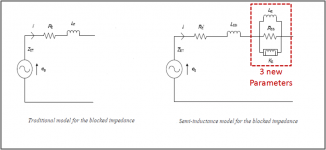
Sorry for the confusion, there ARE a total of 5 parameters, but 2 of them (a series resistance and series inductance) are already in the traditional model. So, you are only keeping track of an additional 3 parameters.It would seem that the Scanspeak data sheets specify five additional parameters for the semi-inductance model, not three
The 2 parameters in common between the 2 models represent different things depending which model is used, so it makes sense that their values will be different.(The values of resistance [Re'] and bound inductance [Le] are different to those specified elsewhere in the sheets for DC resistance [Re] and voice coil inductance [Le]).
Am I missing something here?
Traditional Model
Re = DC resistance
Le = inductance at an arbitrary frequency of 1kHz
Semi-Inductance Model
Re’ = DC resistance + resistance of any shorting rings outside the gap transformer coupled to the voice coil. Depending on the woofer design, this value might be the same as Re, or a few tenths to half an ohm greater than Re. The effects of shorting rings in or very near the gap are captured by Rss.
Leb = inductance of the portion of the voice coil that is more distant from the iron. This parameter mainly affects the impedance in the top 2 octaves. The inductance/semi-inductance of the portion of the voice coil in closer proximity to the iron is captured by the parallel combination of Le and Ke.
BTW, the model began with 15 parameters to describe the magnetic circuit. It took quite some doing to simplify down to a more manageable 5 parameters while retaining the features necessary to capture the variations of woofer motor design.
Ha!it would have seemed more logical for bound inductance be designated as [Leb] rather than [Le], and free inductance to be designated as [Le] rather than [Leb]
Funny thing is, the terms “bound inductance” and “free inductance” do not appear in any of the Thorborg AES papers or other presentations on the subject. I actually had not noticed the terms in the data sheet until you pointed them out. I had always assumed Leb stood for blocked inductance, but not sure that makes sense either. I posed the question to one of the authors of the 2011 AES paper, will let you know what I find out.
Attachments
there ARE a total of 5 parameters, but 2 of them (a series resistance and series inductance) are already in the traditional model. So, you are only keeping track of an additional 3 parameters.
Hi bolserst,
Many thanks for the clarification. Just to check that I now understand correctly - in effect Re and Le simply get a name change to Re' and Leb when used in the semi-inductance model, and the Re' and Leb values given by Scanspeak are substituted for the traditional DC resistance and voice coil inductance values. Is this correct?
Another question for you
. Does the suspension admittance parameter [Ams] also need to be included in the model, or can it be safely ignored?Thanks again for your help!
Kind regards,
David
Thanks mwmkravchenko!
Adding another L to the name works wonders for search results “STEALLUS”
The Voice Coil article on the STEALLUS design is currently available for download.
Attached is a slightly reduced size copy in case the link breaks at some point in the future.
https://pearl-hifi.com/06_Lit_Archive/14_Books_Tech_Papers/Mowry_Steve/Steallus_Motor_Design.pdf
Attachments
That is correct.…in effect Re and Le simply get a name change to Re' and Leb when used in the semi-inductance model, and the Re' and Leb values given by Scanspeak are substituted for the traditional DC resistance and voice coil inductance values. Is this correct?

Personally, I ignore it.Does the suspension admittance parameter [Ams] also need to be included in the model, or can it be safely ignored?
The frequency dependent damping term only affects the mechanical Q, so it is a small player with woofers where electrical damping dominates.
I agree, the response shape certainly does mimic a loss in electrical damping. After reading your paper, I was trying to figure out why the adjustment worked really well for most long stroke drivers, but not all. It confused me why the Le/Re ratio should correlate with loss of electrical damping…but hard to argue with the data you plotted. After finally getting some time to take detailed measurements on a woofer that exhibited significant “inductance hump” it became clear that the hump shape was mainly coming from the LP filtering action of the lossy inductance which is not at all represented well by the single 1kHz inductance value used in most modeling software. Depending on the woofer there can be a small loss in electrical damping at resonance due to the semi-inductance, but it is pretty minor…something akin to adding about 0.5 ohm in series with the voice coil.…My comment about derated motor strength was based on the method I used to create the lossy Le method. As you know, all it does is derate Bl, and IIRC the amount Bl had to be derated to match the measurement was in the ballpark of 20 to almost 40 percent in the drivers I studied. So based on this (the shape of the measured vs simulated frequency response - basically a qtc comparison), it appears as though the driver has lost 20 - 40 percent motor strength compared to what the simple t/s (a simple sim) would suggest.
To illustrate the filtering action I am talking about, I took the blocked impedance R & L values for the semi-inductance parameters and entered them into Hornresp Filter wizard for 20,40,60,80,100,200 Hz. Follow the dot as you flip pages and you can see the match with measurements at each discrete frequency data point. What the semi-inductance model does is provide the continuously varying blocked impedance to include in the calculations.
Attachments
Thanks bolserst.
I have started looking at the possibility of including the semi-inductance model as another option in Hornresp (the existing Lossy Le model option developed by 'just a guy' would be retained).
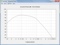
The attachment shows the power response for the ScanSpeak 32W/4878T00 subwoofer mounted in an infinite baffle, using the semi-inductance model.
For the sake of completeness I will probably also consider making allowance for the admittance parameter, even though it seems to make little difference to the results, as you say.
It may take a while for the new production version of Hornresp to be released. The easy part is coding the calculations. The more time-consuming parts are sorting out the user interface to enable the required "advanced parameter" values to be entered, and changing the data files to permanently store the required extra parameters. I know what I want to do, but getting everything to work as intended can sometimes be quite a challenge.
Kind regards,
David
I have started looking at the possibility of including the semi-inductance model as another option in Hornresp (the existing Lossy Le model option developed by 'just a guy' would be retained).
The attachment shows the power response for the ScanSpeak 32W/4878T00 subwoofer mounted in an infinite baffle, using the semi-inductance model.
For the sake of completeness I will probably also consider making allowance for the admittance parameter, even though it seems to make little difference to the results, as you say.
It may take a while for the new production version of Hornresp to be released. The easy part is coding the calculations. The more time-consuming parts are sorting out the user interface to enable the required "advanced parameter" values to be entered, and changing the data files to permanently store the required extra parameters. I know what I want to do, but getting everything to work as intended can sometimes be quite a challenge
.Kind regards,
David
Attachments
I agree, the response shape certainly does mimic a loss in electrical damping. After reading your paper, I was trying to figure out why the adjustment worked really well for most long stroke drivers, but not all. It confused me why the Le/Re ratio should correlate with loss of electrical damping…but hard to argue with the data you plotted. After finally getting some time to take detailed measurements on a woofer that exhibited significant “inductance hump” it became clear that the hump shape was mainly coming from the LP filtering action of the lossy inductance which is not at all represented well by the single 1kHz inductance value used in most modeling software. Depending on the woofer there can be a small loss in electrical damping at resonance due to the semi-inductance, but it is pretty minor…something akin to adding about 0.5 ohm in series with the voice coil.
To illustrate the filtering action I am talking about, I took the blocked impedance R & L values for the semi-inductance parameters and entered them into Hornresp Filter wizard for 20,40,60,80,100,200 Hz. Follow the dot as you flip pages and you can see the match with measurements at each discrete frequency data point. What the semi-inductance model does is provide the continuously varying blocked impedance to include in the calculations.
Great information as always, thanks.
Thanks bolserst.
I have started looking at the possibility of including the semi-inductance model as another option in Hornresp (the existing Lossy Le model option developed by 'just a guy' would be retained).
The attachment shows the power response for the ScanSpeak 32W/4878T00 subwoofer mounted in an infinite baffle, using the semi-inductance model.
For the sake of completeness I will probably also consider making allowance for the admittance parameter, even though it seems to make little difference to the results, as you say.
It may take a while for the new production version of Hornresp to be released. The easy part is coding the calculations. The more time-consuming parts are sorting out the user interface to enable the required "advanced parameter" values to be entered, and changing the data files to permanently store the required extra parameters. I know what I want to do, but getting everything to work as intended can sometimes be quite a challenge
Kind regards,
David
This is fantastic. I'm sure Ricci will be on board to include these parameters for models he tests on data-bass, and hopefully he still has screenshots of all his previously measured drivers that he can add to the driver collection that's already there.
I felt the tide going this way so I've already imagined what this feature might look like. Perhaps toggling through "Le" (normal, lossy le, semi inductance le) by double clicking them, and maybe semi inductance Le could be green. Then if semi inductance model is chosen (green Le), a new small window could pop up asking for the 3 extra parameters. If you needed to change these parameters you would cycle through until Le is green again and the box would pop up again.
Not sure how else it could be done, it would be tough to fit 3 more boxes on the input screen.
But I'm sure you probably already have your own ideas that are better.
Looks like the old trade off of complexity for size situation. Always an interesting discussion.
If a person has the luxury of a dedicated room size become less and issue. IF the wife doesn't like my 6.5 cubic foot boxes she doesn't need to come in that room. However, she like the sound and listens too.
If a person has the luxury of a dedicated room size become less and issue. IF the wife doesn't like my 6.5 cubic foot boxes she doesn't need to come in that room. However, she like the sound and listens too.
Not exactly. It's a tradeoff between driver design and motor cost versus budget.
I'm currently working on a design for drivers that are perfectly happy in a 2.5 litre enclosure and should be able to hit 95db in that small volume.
As in most things engineering can get you where you want to. The cost on the other hand is large.
Many things are possible. We just have to be willing to pay for them.
First off, i haven't replied for a while as i have a new PC so i've been Very busy optimising the OS & reinstalling All my programs & Data etc etc. LOTS !
I read the Steve Mowry PDF on Steallus & a few articles on his LinkedIn page. Wow, clever guy !
I tried to go to his www linked in the PDF, but it seems to not exist anymore ! Anybody got his new one ?
*
Interesting discussions etc, long may it continue, so Thanx to all who have & are contributing etc. & to Sir David McBean for the extra coding in HR
so i've been Very busy optimising the OS & reinstalling All my programs & Data etc etc. LOTS !I read the Steve Mowry PDF on Steallus & a few articles on his LinkedIn page. Wow, clever guy !
I tried to go to his www linked in the PDF, but it seems to not exist anymore ! Anybody got his new one ?
*
Interesting discussions etc, long may it continue, so Thanx to all who have & are contributing etc. & to Sir David McBean for the extra coding in HR
Nope Steve is officially retired. He doesn't have a website that I know of.
And you are describing something that I have to do shortly. I hates reinstalling windoz. And I hate reinstalling all the programs much more. An enormous pain on an engineering computer. That I can tell you for sure!
And you are describing something that I have to do shortly. I hates reinstalling windoz. And I hate reinstalling all the programs much more. An enormous pain on an engineering computer. That I can tell you for sure!
- Status
- This old topic is closed. If you want to reopen this topic, contact a moderator using the "Report Post" button.
- Home
- Loudspeakers
- Subwoofers
- Inductance Cancellation Techniques