Riccardo,
Clamping problem?
Take a look here :http://www.diyaudio.com/forums/showthread.php?s=&threadid=32057&highlight=
May give you some ideas for a fix!
Kind regards,
Ashley.
When i put the cd in the drawer, and i push close, the drawer it's ok, but the cd, inside, jump out of right position, the clamper can't make anything, and cd don't rotate.
Clamping problem?
Take a look here :http://www.diyaudio.com/forums/showthread.php?s=&threadid=32057&highlight=
May give you some ideas for a fix!
Kind regards,
Ashley.
You're very kind, thanks a lot.
I did buy a service manual from your ebay link just now.
best regards
Riccardo
Clamping problem?
Take a look here :http://www.diyaudio.com/forums/showthread.php?s=&threadid=32057&highlight=
May give you some ideas for a fix!
Kind regards,
Ashley. [/B][/QUOTE]
I did buy a service manual from your ebay link just now.
best regards
Riccardo
Clamping problem?
Take a look here :http://www.diyaudio.com/forums/showthread.php?s=&threadid=32057&highlight=
May give you some ideas for a fix!
Kind regards,
Ashley. [/B][/QUOTE]
Hi,
I was sceptical about what a new clock could bring to these old Philips chipset cd players.
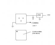
I knocked together a cheap clock the other day from parts found at http://www.rapidelectronics.co.uk/ (oscon caps, TTL 11.2896 crystal oscilator module, 8 pin dil socket, small stripboard etc). It took about an hour to build, I then triple checked wirings/ solderings/ layout, and then measured the voltage on the outputs of the new clock (2.4V) when unconnected. Connected it up, listened, and could instantly tell that the player had changed for the better (less fatiguing, more foot tapping).
As I don't have the equipment to measure jitter I mounted the canned oscilator on a 8dil socket so I can easily fit a Tent oscillator ( which is potentially low jitter) in the future.
I had thought about building a kwak clock but I came to the conclusion that I wouldn't be able to get the layout right.
Kind regards,
Ashley.
I was sceptical about what a new clock could bring to these old Philips chipset cd players.
I knocked together a cheap clock the other day from parts found at http://www.rapidelectronics.co.uk/ (oscon caps, TTL 11.2896 crystal oscilator module, 8 pin dil socket, small stripboard etc). It took about an hour to build, I then triple checked wirings/ solderings/ layout, and then measured the voltage on the outputs of the new clock (2.4V) when unconnected. Connected it up, listened, and could instantly tell that the player had changed for the better (less fatiguing, more foot tapping).
As I don't have the equipment to measure jitter I mounted the canned oscilator on a 8dil socket so I can easily fit a Tent oscillator ( which is potentially low jitter) in the future.
I had thought about building a kwak clock but I came to the conclusion that I wouldn't be able to get the layout right.
Kind regards,
Ashley.
riccardo said:Hi. could you post the schematics and some picure , oro link,of your new clock?
Thanks.
R
Hi,
Well I just wanted to test a clock change first.
I just got a L7805 regulator,oscon capacitor , a oscillator module, and connected them together.
This isn't really ideal so maybe next week I will build the powersupply from one of the attached links now that I know how large the effect of the clock is!
Reading on the forum, and net it seems oscillator design is a black art so probably best to stick to proven designs. Also it seems few people actually have the equipment to measure jitter properly which explains the plethora of aftermarket clocks available.
For psu see:-
http://www.wenzel.com/documents/finesse.html
http://www.tentlabs.com/ProductEntities/XO/XO.html
For notes see:-
http://www.diyaudio.com/forums/showthread.php?postid=639462#post639462
http://www.diyaudio.com/forums/showthread.php?postid=640127#post640127
Kind regards,
Ashley.
Attachments
Hi,
Today I replaced the saa7220 decoupling capacitor with an oscon variety. This has made a huge difference:- piano sounds improved, echo effects show through, and electric guitar effects can be heard.
Even with the standard lm833 op amps in there this player is now easy to listen to.
So I will continue working on the digital side of the player....
-decouple tda1541a power supply pins with oscons
-decouple microcontroller with oscons
-copper shielding for chips
-heatsink for tda1541a?
Again, that underneath access panel is so handy.")
..as for groundplane/ track 'issues' I will have to read up on the forum.
Kind regards,
Ashley.
Today I replaced the saa7220 decoupling capacitor with an oscon variety. This has made a huge difference:- piano sounds improved, echo effects show through, and electric guitar effects can be heard.
Even with the standard lm833 op amps in there this player is now easy to listen to.
So I will continue working on the digital side of the player....
-decouple tda1541a power supply pins with oscons
-decouple microcontroller with oscons
-copper shielding for chips
-heatsink for tda1541a?
Again, that underneath access panel is so handy.
..as for groundplane/ track 'issues' I will have to read up on the forum.
Kind regards,
Ashley.
GReat.
Have you some photo?
ciao
R
Have you some photo?
ciao
R
ash_dac said:Hi,
Today I replaced the saa7220 decoupling capacitor with an oscon variety. This has made a huge difference:- piano sounds improved, echo effects show through, and electric guitar effects can be heard.
Even with the standard lm833 op amps in there this player is now easy to listen to.
So I will continue working on the digital side of the player....
-decouple tda1541a power supply pins with oscons
-decouple microcontroller with oscons
-copper shielding for chips
-heatsink for tda1541a?
Again, that underneath access panel is so handy.
..as for groundplane/ track 'issues' I will have to read up on the forum.
Kind regards,
Ashley.
Digital Supply!!!!
The same +10V supply feeds the servos and the +5V regulator. This +5V regulator supplies the digital section and the DAC. You probably need to connect to supply to your clock PCB somewhere between the 6,800uF cap and the +5V regulator. However, a better result should be obtained by giving the clock its own transformer and supply.
The same +10V supply feeds the servos and the +5V regulator. This +5V regulator supplies the digital section and the DAC. You probably need to connect to supply to your clock PCB somewhere between the 6,800uF cap and the +5V regulator. However, a better result should be obtained by giving the clock its own transformer and supply.
all done, it's playing...
Ciao
I did connect the new clock Pcb (from Elso Kwack, txs) before voltages +5 and +6 digital regulators.
After that, i did connect clock output directly to pin 11 of SAA 720, and ground to PIN 12.
Obviously, i removed, at first, two cap of 47pF at oscillator leads.
What is, please, Jean Paul, the reason of your suggestion?
Excuse my english..
txs, Bye.
Riccardo
jean-paul said:Please try a 47 Ohm resistor in series with the output of the new clock......
Ciao
I did connect the new clock Pcb (from Elso Kwack, txs) before voltages +5 and +6 digital regulators.
After that, i did connect clock output directly to pin 11 of SAA 720, and ground to PIN 12.
Obviously, i removed, at first, two cap of 47pF at oscillator leads.
What is, please, Jean Paul, the reason of your suggestion?
Excuse my english..
txs, Bye.
Riccardo
ash_dac said:Riccardo,
Out of interest where did you get the Elso Kwack pcb from?
I haven't bought the service manual yet.
What plans do you have for the player?
Kind regards,
Ashley
Ciao Ashley
the pcb directly from...Elso kwack, obviously.
Kwack clock 7.
The 40 it's the "pole" of my stereo.
My "old" marantz cd 40 it's like a Ferrari's car.
I put inside the cdp a transformer's output By Royal Device, (could you see on web) and now the new clock.It sound superb!
(i did buy the service manual on ebay, do you remember?)
ciao kind regards,
Riccardo
ash_dac said:Riccardo,
I will probably replace the tda1541a R1 to S1 variety.
I have found a new cheap source for S1 variety
Kind regards,
Ashley.
Ciao!
mhhh..let me know something more...please.I'm very interested 'bout that.
(pvt, if you prefer)
I have two or three old cdp with tda1541A, but nothing with mr. S1.
All i know about TDA is that St Microelectronis seems produce still them unitl about 5 years ago..
But i'm no sure at all.
ciao
Riccardo
Ciao!
mhhh..let me know something more...please.I'm very interested 'bout that.
(pvt, if you prefer)
I have two or three old cdp with tda1541A, but nothing with mr. S1.
All i know about TDA is that St Microelectronis seems produce still them unitl about 5 years ago..
But i'm no sure at all.
ciao
Riccardo,
Your email does not seem to work. Can you enable it ?
Kind regards,
Ashley.
Basic suggestion about decoupling SAA
Hello.
Cause i'm a little be newbie, i need please, if is possible, some basic suggestion about decoupling supply of SAA7220p/B and TDA1541A (S1) in a old cd40.
I have some Oscon 6,3V 220uF, but i did'nt understood the schematic, so i did'nt known the right pin to decouple, with oscon cap.
I would know, too, please, also the right position of 100uf 20V cap.
Thanks
RR
[QUOTE
Here are Jean-Paul's standard CD60 mods (from DiyA):
CD60 has a CDM4/19, plastic chassis and a completely different mainboard with an integrated power supply. I once modded a CD60 SE or KI that was flawed with some design errors that were not in the original one. Check which version you have.
It is a good cdplayer that much resembles the Philips types of those days. As with those Philips types I would decouple SAA7220 really well with 220 uF OSCON.
Replace output opamps with OP249 ( used that one at that time ), OP275 or better: wait for Rbroers output pcb's ! Output caps can be Nichicon MUSE ( leave them were they are or replace them for the same types ) or standard electrolytics which I would replace for a more audiophilic type. There is a member here ( Wkcheng I think ) that sells good bipolar electrolytics for audio. Please check if the output opamps have decoupling caps at all. In some Philips cdplayers with the same pcb they are omitted.
Decouple the servo opamps well. Replace all electrolytics with better types like Panasonic FC or BCComponents series 038. The original ones are worn out because of age. A Guido clock DIY with a separate transformer and supply will make the most difference but beware. The plastic case allows RF to leave the cdplayer in original state already and it'll be worse with a new clock. Better use metal screen against the "walls" of the plastic chassis with a connection to GND otherwise your radio and tv will notice when the cdplayer is on
A careful examination of ground routing is something for the experienced but it's worth the energy. Please disconnect the cables to the output with the potentiometer if you don't use the regulated output. You'll be surprised how much sound will be better. ( you cut approx. 25 cm of cable by doing so ). That counts for the headphone output as well. When doing so you can remove the headphone opamp IIRC. Use dampening/damping material like Bostik for the upper metal cover.
* watch out with touching the mainpcb of cd60. The copper is unprotected and it will corrode after is is touched * It is possible to coat it with polyurethane spray. I don 't feel for a discussion about the negative effects of that. It does have an influence though. Please cover *all* connectors and remove the cdm when spraying the board !!!!
These mods are more or less the standard approach of mine with the CDM oldies. There are more possibilities however like using an extra 7805 for SAA7220 alone or adding a new separate supply for the output stage.
I don't have a manual of this one but it is the standard Philips mainboard so you can use almost any manual you want of similar types.
Be careful with desoldering parts as the pcb tracks peel off easily. Better use desolder braid for that....
quote:
Comments from other members
Change all the rectifiers diode(with snubber network) to the fast recovery UG2B. Replaced some of the jumper wire with Ferrities bead for most of the supply lines.
Currently working on the ground looping. Detected that the SAA7310 is within the same loop as the servo amp(Motorola TCA0372 nd TDA8808/9 servo processor. I am now confused whether to group the TDA8808/9 and the SAA7310 in the same ground path cause they shared the same +5V regulator . But I am sure that the TDA8808/9 will be pretty noisy.
At the moment I settle for ground sharing of TDA8809/9 and TCA0372. The other ground will be shared by all others digital ICs.
Feeding the TCA0372 with it's own supply and ground is the best solution but it takes space which you don't have in that one. Personally I think it s too much work but it can be done in some of the oldies.
Feed the SAA7220 with it's own supply or decouple it with OSCON.
I need your advice on the ground looping. Is those grounding scheme that i applied is the correct way. I meant grouping the TCA0372 with the TDA8808/9 together and SAA7310/PCF3523P another separate group.
Some CD630 mods:
Well, started from +-15 v PS. Took of 7815/7915 and capacitors before and after. Diodes remain. Capacitors before regulator chanched to Elna Silmic 1000x35 - they are big, so one placed vertically in the same holes and another one lying on the bottom side of printed board (PB). After regulator Elna Starget 470x35 - both also on the bottom side of PB. Essentially regulator made on M5230L + transistors (Rohm) from datasheet. Placed also on the bottom side in the holes from 7815/7915. Capacitors from consume side (TDA1541 - 15V, LM833) changed to BG ST 100x16v. Resistors 10 ohm in-series remains. Capacitors of digital supply TDA1541 (+ - 5 v) changed to BG NX 220x6,3v. Digital power supply remains. O.K. Results: CD listening is YES "Magnification". Much & MUCH clearly, more opened and a new voices & instruments appeared !!! Sadly dislocate absence of deep , controlled bass. Without bas overall don't like this sound. Now will do digital PS on M5290 & clock. Will check. Heard that it's very hard to extract a deep bass from TDA1541A. What's your opinion?
The original capacitors are Nichicon 470x35 v and they are ~ three times smaller than Elna Silmic 1000x35, so I sad "big" just because of the can size ( 18 x 35,5, mm ) and yes, they are the biggest ones in can size that would fit, but not in the values. I just have them, so I used them. You can use any other capacitors even with the bigger values with ~ this sizes (Panasonic FC or FJ for example), but values bigger than 1500 mF would not be reasonable I think. I suggest you to put AFTER the regulator Black Gate's FK 470 mF (220 also will be O.K.) x 16 v and from the consume side also let's say 50-100 mF x16 v. They are making VERY good job. I'm already ordered FK and will change the presence ones for them.
[/B][/QUOTE]
changing supplys caps
Hello.
I'm restoring this old cdplayer, and at first i did change the cap after the trasnformer, with panasonic FC same value.
I have a doubt about the caps after the voltages regulator.
So, my question is: what caps and values i could use for 47uF 25V and 33 mF 16 volts (old caps are Nichicon VX(m))?
And, again, what kind of caps? Sanyo OS CON?
Thanks a lot, i need some suggestion 'cause caps change drammatically the sound of cdp.
TXS.
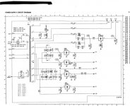
In attacched schematics.
Riccardo
Hello.
I'm restoring this old cdplayer, and at first i did change the cap after the trasnformer, with panasonic FC same value.
I have a doubt about the caps after the voltages regulator.
So, my question is: what caps and values i could use for 47uF 25V and 33 mF 16 volts (old caps are Nichicon VX(m))?
And, again, what kind of caps? Sanyo OS CON?
Thanks a lot, i need some suggestion 'cause caps change drammatically the sound of cdp.
TXS.
In attacched schematics.
Riccardo
Attachments
changing supplys caps
Hello.
I'm restoring this old cdplayer, and at first i did change the cap after the trasnformer, with panasonic FC same value.
I have a doubt about the caps after the voltages regulator.
So, my question is: what caps and values i could use for 47uF 25V and 33 mF 16 volts (old caps are Nichicon VX(m))?
And, again, what kind of caps? Sanyo OS CON?
Thanks a lot, i need some suggestion 'cause caps change drammatically the sound of cdp.
TXS.
In attacched schematics, i hope more readable.
Ciao riccardo
Attachments

- Status
- This old topic is closed. If you want to reopen this topic, contact a moderator using the "Report Post" button.
- Home
- Source & Line
- Digital Source
- Improving my old Marantz CD40?????