Dear DIY Audio Community,
In this thread I like to discuss a amplifier / speaker protection circuit that I designed.
Foreword:
I once fried a speaker by turning equipment on the wrong order.
As a countermeasure I improvised a circuit to delay speaker connection on power on.
So far so bad.
I like to get rid of the improvised delay circuit and have a real protection circuit instead.
There are a lot of modules available on the market, some even extremely cheap to buy.
I also found lots of circuits.
But none work the way I need them to.
My requirements for a speaker protection circuit:
1. Delayed connection of speaker after power on.
2. Instant speaker disconnection on power off.
3. Quick speaker disconnect in case of DC on amplifier output.
4. Latch relays off when any fault occurred.
5. Can be used for my dual mono design without hard wiring ground of the two amps together.
6. Can be built from parts I have at home or can source easily and cheap.
7. Is component selection invariant.
8. Is supply invariant from 12V to 24V.
9. Can be configured in a lot of ways so that others can make use of it easily.
From the circuits I found I liked the DIY Audio circuit best that is also used for the boards in the DIY Audio store.
It already fulfills requirements 6 and 7 and 8.
But this circuit has serious drawbacks I tried to get rid off.
I spent lots of time developing a circuit that hopefully does what I envisioned.
Circuit description:
The circuit has following modules:
1. AC to DC rectifier
2. Linear regulator
3. Relay status indicator
4. Turn on delay circuit
5. Latch circuit
6. DC detection
7. Instant off on AC loss
Module description in detail:
1. AC to DC
This is a standard rectifier. Nothing to explain.
2. Linear regulator
This is made up of discrete parts and a very basic circuit. I'm not sure whether this is a good design since I've never done any before and don't know the pitfalls. Feedback from the great engineers of the DIY community is very appreciated.
3. Relays status indicator
I used this circuit from the DIY Audio schematic. I find it a nice solution with the blinken light. Just tweaked component values to my needs. The LED blinks until the relays are engaged and then lights constantly.
4. Turn on delay circuit
I started with the DIY Audio schematic but added a Schmitt trigger for clearly defined switching of the relays because this was missing.
5. Latch circuit
A failure is a potentially catastrophic event. Should the speaker survive the first wave and the relays succeed to disconnect the speaker in time I don't like to give the disaster a second and third chance to ruin my speakers. This is why I designed this latch circuit to keep the relays disengaged after a fault occurred.
The latch is triggered by pulling the node called DC-DETECT to ground. So this can be triggered by any open collector output.
6. DC Detection
Again I used the DIY Audio circuit to start with but found it has two drawbacks:
First it is not sensitive enough. This may be intentional to avoid false error detection.
Second is that it can't detect simultaneous failure of both amps with one going positive and one going negative DC. Murphy will make that happen for sure especially since the DC event is a catastrophic failure condition and everything bad that is possible will happen here.
I also added resistors in the ground path to separate the two ground from each other. Hope this works as intended. For a stereo amplifier I recommend to leave R24 and R25 away and instead double the value of R22 and R23.
7. Instant off on AC loss
I found this circuit on the web and it does exactly what I need. Once the AC goes off the relays shall go off too quickly. There might be too much charge in the power supply capacitors that delay relay turn off. So the AC is sensed and makes the latch trigger once gone.
The circuit simulation shows that the circuit seems to behave the way I intended.
Turn off DC threshold is ~2V.
Relay turn off delay is ~70ms.
Please review the circuit and let me know your thoughts.
Did I get something totally wrong?
Do you have ideas to improve the circuit?
Thank you very much and best regards
Lee
Attachments:
- Schematic as PDF
- Schematic as LT Spice schematic
- Screenshot of operation with latch disabled to show every case that is covered
Hi Lee,
Are you providing/selling the PCB's for this project ?
- Can the delay on time at start up be increased to about 9-10 seconds ?
- I was planning on using Rod Elliott's mosfet relay (project 198) for this, especially the diode emulator version:
Project 198
using these puppies: IRF150P220XKMA1 (https://www.infineon.com/dgdl/Infin...N.pdf?fileId=5546d46266a498f50166aca241ac65c9), with 2.5milliohm on resistance and more than 100 amps easy. There would be virtually no power dissipated on them, even at full amplifier power.
Thanks
Hi Cakyol,
yes, I would offer PCBs once I know that the concept works fine. The circuit is a bit unconventional and I like to make sure it really works. I won't sell PCBs prior to building and testing one module myself.
I already have PCBs and parts, but wanted to finish another module first (which I had to re-spin PCBs for and migrate the assembly, but I'm almost done building this one).
The other module provides 12V DC for powering the speaker protection module and provides an AC loss signal (see schematic attached) to trigger instant speaker disconnect in case mains AC is lost.
The turn on delay is defined by R18 and C2, which can be adjusted as required. If I remember correctly, the values in the schematic shown here aim for something between 5 to 10 seconds delay. It should be easy to adjust for >10 seconds.
The MOSFETs you plan to use seem to be an excellent choice for amplifiers using somewhat normal supply voltage. I used higher voltage ones for testing with my monster 1 kW amp.
The Si8752 is a very interesting component. What I like most about this one is that it has Miller capacitance control. I can't remember why I decided to use the classic photovoltaic drivers instead. Probably because I feared soldering the SOIC-8 package.
Short explanation of the AC loss detector circuit:
D2 and D3 are connected to the transformer secondary ahead of the bridge rectifier, i.e. fed with AC. The rectified positive pulses make Q1 preventing C3 to charge up. In case mains AC is lost, open collector output Q2 becomes activated and resets the start-up delay of the speaker protection circuit.
Attachments

Thanks for the excellent information Lee.
Please let me know when you have finished testing your system so I can follow up.
Thanks again.
Please let me know when you have finished testing your system so I can follow up.
Thanks again.
Hi Cakyol,
yes, I would offer PCBs once I know that the concept works fine. The circuit is a bit unconventional and I like to make sure it really works. I won't sell PCBs prior to building and testing one module myself.
I already have PCBs and parts, but wanted to finish another module first (which I had to re-spin PCBs for and migrate the assembly, but I'm almost done building this one).
The other module provides 12V DC for powering the speaker protection module and provides an AC loss signal (see schematic attached) to trigger instant speaker disconnect in case mains AC is lost.
The turn on delay is defined by R18 and C2, which can be adjusted as required. If I remember correctly, the values in the schematic shown here aim for something between 5 to 10 seconds delay. It should be easy to adjust for >10 seconds.
The MOSFETs you plan to use seem to be an excellent choice for amplifiers using somewhat normal supply voltage. I used higher voltage ones for testing with my monster 1 kW amp.
The Si8752 is a very interesting component. What I like most about this one is that it has Miller capacitance control. I can't remember why I decided to use the classic photovoltaic drivers instead. Probably because I feared soldering the SOIC-8 package.
Short explanation of the AC loss detector circuit:
D2 and D3 are connected to the transformer secondary ahead of the bridge rectifier, i.e. fed with AC. The rectified positive pulses make Q1 preventing C3 to charge up. In case mains AC is lost, open collector output Q2 becomes activated and resets the start-up delay of the speaker protection circuit.
Hi again Lee,
In your write up at the beginning of this thread, you mentioned that your design is for a supply voltage of 12 - 24 VDC invariant.
I am planning on driving it using the aux secondary of the amp's power transformer, 12VAC, giving about 18 VDC after rectification. I presume that will be ok.
Also, on your AC loss detection (so that the relays turn off immediately), what is the min - max AC voltage range ? My main amp is driven from about 60 VAC and my aux is 12 VAC. Which one is recommended ? I would prefer to use the lower voltages in everything if possible but just asking.
Thanks
The AC loss detection seems to work fine with any voltage - at least according to simulation.
The whole speaker protection circuit should work with a wide supply range as well. I simulated this with 10 and 90V.
Note that the 1845 / 992 transistors chosen are only suitable up to maximum 50V roughly. For higher voltage, transistors with better SOA would be required. The SC3503 / SA1381 should do fine (haven't simulated this though, but will test it in real life).
The circuitry is mostly supply voltage invariant.
Please find attached two simulation results that show how the circuit reacts to different conditions.
The plots show the current through the status LEDs and the SSR. Also shown is the supply voltage, the reset switch activation and AC loss trigger.
Events:
15s: High positive DC voltage at loudspeaker output
17s: User reset
30s: Negative low DC at LS output
36s: User reset
50s: Positive low DC at LS output
56s: User reset
67s: AC loss
Note the supply is terribly noisy on purpose.
In simulation, I used 100k and 47uF for setting the start-up delay. Delay time has some dependence on supply voltage.
Attachments


For the control circuitry you can use any supply you may have.
The output stage power supply would be fine, although high supply voltage requires more powerful transistors and more heat dissipation in the control circuitry.
Any auxiliary power supply would do as well. I would say this is preferred due to lower power dissipation and cheaper low power transistors for the control circuitry.
The control circuitry is galvanically isolated from the DC detection and the SSR so the floating rail boost supply for the front end would be a good choice as well.
I wanted to have this level of flexibility so that the module is useful even if you don't have any auxiliary control supply. Or in case you have an auxiliary supply, but that is used for rail boosting and rides atop one power rail.
The control circuitry could be heavily stripped down in case the status LEDs were not required. I like the status LEDs and this is why the circuit is that complex and the boards that huge.
In my case PCB dimension was fixed anyway, since this PCB is inside a stack of three PCBs with all same size. So I just made use of the real estate available.
Located below in the stack is the transformer start-up control that also supplies 12VCD for powering the speaker protection module and whatever I might need a 12V aux supply for.
Located above the speaker protection module, there is the audio input module, which could be some op-amp based pre-amp, volume control or just audio input transformer in my case.
The decision to put the AC loss detection on a different PCB was made because I don't like to wire noisy AC signals all around inside the amp chassis. Plus I find that a power supply should report its status so the AC loss detection is on the PCB the power supply is on.
Hi Lee,
You mentioned that R18 & C2 control the start up delay.
Looking at the schematic you posted in your VERY FIRST message on this thread, that does not quite look correct... or am I not seeing it correctly ?
Or have you posted another updated schematic somewhere in the thread that I should refer to, instead of the very first one you posted ?
To me it looks like R15 & C10 seems to control it. If that is correct, usually increasing capacitance (C10) increases its footprint, so I would probably increase R15, but then again, if that is increased too much, will Q14 turn on with reduced current ?
Thanks
This project has changed dramatically from where it started.
What we are discussing now, has very little to do with the initial concept. The new schematic is presented here: Improved speaker protection circuit
What we are discussing now, has very little to do with the initial concept. The new schematic is presented here: Improved speaker protection circuit
Small update:
I started populating the PCB and the DC detection seems to work.
I expect further progress in a few weeks because of missing material and time.
I started populating the PCB and the DC detection seems to work.
I expect further progress in a few weeks because of missing material and time.
Another update on progress:
I have the assembly complete for one channel.
Assembly was a nightmare.
When I started, I realized that the resistor values do not make sense. This is because initially the circuit was designed for 12V operation. Later I had the idea to make it supply invariant. I never bothered to care about power dissipation in resistors and transistors. So I had to recalculate everything again. I did this during assembly and this distracted me so that I accidentally swapped almost every NPN for a PNP and vice versa. Rework was annoying. I should win the golden solder wick award for stupidity.
Finally, the circuit worked as expected.
I tested operation from 12V only.
1.5V DC does not make the detection trigger, but 3V does and from my perception, instantly.
During simulation I found out that the circuit should work using MJE340 and MJE350 as power transistors. However, I don't have any and chose different ones in TO-220 package instead. Assembly is a bit crooked because of that.
I kept the KSC1845 and KSA992 because I had some at hand. Those are obsolete now just like almost every other THT package transistor that could be useful. Probably KSA1013 and KSC2383 are a good alternative. Audio grade transistors are wasted in this circuit.
Now I will continue with testing the circuit in reality. My equipment is a bit limited, but somehow I will figure out whether it performs like is should.
Once performance is confirmed, I plan to share an updated schematic. Pretty much all component values have changed.
Attachments

Today I tested the circuit.
First test setup was starting low with the supply voltage of 12V and 9V DC (block battery) at the loudspeaker.
Response time is ~20ms, which is somewhat expected since the low pass is set to 10Hz. Actually it should respond within 100ms.
Oscilloscope was set to 5V/div and 50ms/div.
First test setup was starting low with the supply voltage of 12V and 9V DC (block battery) at the loudspeaker.
Response time is ~20ms, which is somewhat expected since the low pass is set to 10Hz. Actually it should respond within 100ms.
Oscilloscope was set to 5V/div and 50ms/div.
Attachments


Last edited by a moderator:
I feel tired and won't do HV testing with 90VDC today.
Yesterday, I almost electrocuted myself accidentally by touching the mains (230VAC here!) and I don't like to complete the job today.
However, prior to absence for some time, I like to post a teaser:
The module I'm building right now is maybe not what the typical DIYer wants.
I just designed one channel and the second channel was copy and paste. This reduced my PCB design work, but resulted in a lot of redundant circuitry. I have the PCB real estate anyway since the board is located inside a stack of similar sized boards so the lazy way seemed just fine. Solder more, click less
I invested some time into designing a "cummunity edition" in case somebody is interested in the project:
Attached the block diagram of the community edition design and draft of the assembly drawing.
Yesterday, I almost electrocuted myself accidentally by touching the mains (230VAC here!) and I don't like to complete the job today.
However, prior to absence for some time, I like to post a teaser:
The module I'm building right now is maybe not what the typical DIYer wants.
I just designed one channel and the second channel was copy and paste. This reduced my PCB design work, but resulted in a lot of redundant circuitry. I have the PCB real estate anyway since the board is located inside a stack of similar sized boards so the lazy way seemed just fine. Solder more, click less
I invested some time into designing a "cummunity edition" in case somebody is interested in the project:
- I removed all redundant control circuitry and now both channels share the same control and are operated simultaneously.
- I added the AC loss detection.
- The terminals for the amplifier supplies are optional anyway, not really necessary and the performance improvement of connecting them is likely only small so I removed the terminals.
- Also, now having the AC on board, I added a bridge rectifier to the AC and a capacitor to let the module generate its own unregulated supply voltage. Maybe I can even squeeze a regulator on the PCB, but I don't think it will fit. Now you only need to connect any transformer secondary winding. Of course, using a DC supply instead is still possible. Just leave away the bridge rectifier.
- I added cage clamp terminals as alternative to the Speakon connectors because not everybody may like those connectors. I install Wago 236 series cage clamp terminals for all power connections (love them), but Faston blades should fit instead as well (seem to be popular in DIY).
- PCB size was reduced by 20mm.
Attached the block diagram of the community edition design and draft of the assembly drawing.
Attachments


Today I progressed with testing the circuit.
At 25V supply voltage and 25V DC applied to the loudspeaker output and a 4 Ohm resistor load, the reaction time is roughly 18ms.
I also tested this with a real loudspeaker instead. The only one I had at hand was a Sony / Seas KT25F tweeter. Reaction time is similar here and the tweeter survived.
I took apart my power amplifier in order to have proper access to the 90V supply. I noticed that the protection circuit misbehaves above roughly 80V supply voltage. It continuously alerts that there is DC present while this is not true. It turned out that the AQY282EH opto-MOS is rated for maximum 60V only and goes into breakdown above 80V, causing the false alert. Both the opto-MOS and the tweeter survived, but I didn't succeed to record the scope.
Honestly, I didn't expect that the circuit could protect a tweeter. While the tweeter still tweets, it might have suffered mechanical damage by gross overdrive during the 18ms 80V DC burst. Right now I can't find out whether this might have happened or not.
I will probably repeat the test at 90V, but improvise to lower the supply voltage for the protection circuit a bit so that the opto-MOS does work properly.
Again, the time window for doing experiments has closed and I can't proceed for over a week now.
Attachments


I finished verification of the protection circuit this evening.
The last test was to power the protection circuit using a 9V battery and to apply 180V Dc to the loudspeaker output.
I'm having "bad oscilloscope day" and was unable to record this event using the oscilloscope (don't know why).
While trying to record the turn-off time, I applied 180V DC to the poor little tweeter countless times. It is still alive. Since I took apart my power amplifier, I can't play music right now, but the tweeter plays the square wave signal that the oscilloscope outputs.
Overall conclusion:
The protection circuit works better than I anticipated.
It was never designed to protect a tweeter (that is usually DC protected by the passive crossover anyway). Experiments have proven it can even protect a tweeter with 180V DC applied.
Since I tested all kinds of supply voltage and loudspeaker DC voltage combinations, it is also proven that the protection circuit works with any voltage given the semiconductors are rated sufficiently.
A typical small signal transistor can dissipate up to 500mW so this limits the supply voltage to roughly 16V, which means 12V to stay a below the absolute maximum rating. For higher supply voltages, adequate transistors and even heat sinks are required. For example at 90V supply voltage, the transistor driving the SSR dissipates roughly 3W and the ones driving the status LEDs dissipate 1W each. The MJE340 / MJE350 would be a good choice for high supply voltage operation and each channel needs four such power transistors. When dissipating 3W, a small heat sink would be required at least for the one driving the SSR. All this is possible, but a dedicated low voltage power supply may be more elegant.
Also, the opto-MOS needs to have sufficient voltage rating in case a high voltage supply is used. I just bought the cheapest one which becomes conductive once too high voltage is applied. There are ones with higher voltage rating available though.
The most sensible thing to do is to run the control circuitry using a 12V supply and install any cheap small signal transistors for the control circuitry. This also lowers assembly cost a bit (which is the reason I didn't bother having redundant circuitry worth a few cents). Only the transistors for the DC detection need to have high voltage and power rating since they are subject to the loudspeaker output voltage.
At the end of the odyssey, there is a pretty complex and well performing protection circuitry. Many folks here build whole amplifiers using fewer components. For me it was entertaining and informative and I'm happy with my loudspeaker protection.

Right, I still owe you a schematic update.
Indeed, I figured out some bugs and minor improvements.
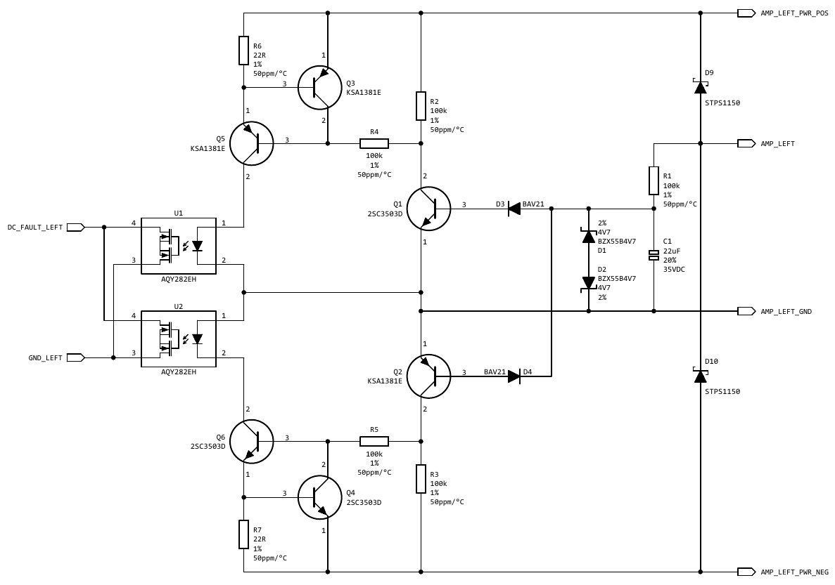
The only novel / unusual circuitry is that of post #89.
Some notes on the schematic in post #89:
Please find attached updated schematic and some notes:
Indeed, I figured out some bugs and minor improvements.
The only novel / unusual circuitry is that of post #89.
Some notes on the schematic in post #89:
- D1 to D4 are useless and can be safely left away.
- A high value discharge capacitor in parallel to C1 might be an idea.
- Also, C1 should be higher in value (33uF to 47uF maybe).
- Q3 and Q4 need a C-E capacitor added (>10nF maybe), else the DC detection circuitry will falsely trigger on high amplitude high frequency material.
Please find attached updated schematic and some notes:
- Note the different connection of the 100k resistors, which may not be a good idea because it may reduce sensitivity. Not 100% sure about this yet. Likely it is better to wire this like in post #89.
- The updated schematic shows different transistors due to better availability / lower component cost. Schottky diodes became normal diodes for the same reason, although Schottky would be preferable IMO.
- Another addition is R48 and R49, which aim to bleed the photo-MOS. Should not be required.
- Reason for some changes (like adding R48 and R49) was that I was having transistors Q40 and Q41 swapped and while figuring out what is wrong, I changed / added circuitry and components. I thought the circuit was too sensitive, but the issue was only due to aforementioned assembly error.
Attachments

Prior to posting an updated schematic, I like to finish PCB design and actually build the new and slightly simplified version. This project is currently not top priority for me.
I encourage you to use parts of the schematic or the whole schematic to design your own PCBs using the components you like / can source locally. My choice may not be your preference. Note that the design can be stripped down dramatically.
Once I have PCBs, you may have one or two in case you don't like to design your own.
Thank you for your quick reply.
Not that i don't want to do my own pcb acc. to your schematics, but i simply have no time that's why im searching some good protection.
im not in hurry...so when you will finished...im here.
Thank you.
Not that i don't want to do my own pcb acc. to your schematics, but i simply have no time that's why im searching some good protection.
im not in hurry...so when you will finished...im here.
Thank you.
Meanwhile I figured out that the PCB design was almost finished pending fixing some DRC errors and cleanup.
I plan to order PCBs this year.
Here is the new assembly drawing. Note that there is some empty space on the left that you can cut off. I need this for compatibility with the first revision.
Nonetheless, this is a rather large PCB.
I plan to order PCBs this year.
Here is the new assembly drawing. Note that there is some empty space on the left that you can cut off. I need this for compatibility with the first revision.
Nonetheless, this is a rather large PCB.
Attachments

- Home
- Amplifiers
- Solid State
- Improved speaker protection circuit