to meet your stated requirement.......................But:
To save what? ..............
I don't plan two separate detectors. Just one board for two channels. But those two channels need to be sensed separately.
- uPC1237 is not an option since it is discontinued.
uPC1237 is NOT discontinued by UTC. It is readily available and it is a very simple and reliable way of protecting speakers. It was discontinued by the inventor NEC long ago that is true. This chip has saved many a loudspeaker. It is famous in the circles of those that build audio without protection but it takes a certain experience for most to embrace this chip and have a long lasting and happy relation

Even if it would be discontinued that would not make a difference when one only needs one or a few. You won't need to replace it every year (I hope
). If you are in doubt just obtain 2 or 3. They are cheap. Even if you would find an NOS NEC one, silicon does not age like milk. This is the TDA1541A of speaker protection. 50 pieces in one buy are 18.5 $ free shipping to Germany included...
http://www.ebay.ca/itm/50pcs-UPC123...734970?hash=item43e81898fa:g:uZsAAOSwh-1W2m-5
Or just 2 for 1.6 Euro shipping included. That is a fraction of the cost of your replacement circuit with smaller size, simplicity and proven reputation as a bonus :
http://www.ebay.de/itm/2pcs-UPC1237HA-C1237HA-PROTECTOR-IC-NEW-C1237/250851885187
* In any case and whatever circuit you will use: please use an over rated high current relay with hard silver contacts. Schrack makes some very nice ones. If you are worried you could use 1 relay per channel with both contacts in parallel.
Last edited:
Proven design for multi-channel DC sensing
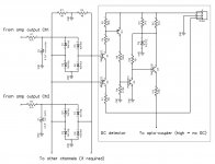
Here is the way we do it in our "21-st century control board".
Single DC detector, separate independent integrators, serving as many channels as required - no limit, literally.
Easy scaling - to add more channels, you just need to add one resistor, one cap and one small signal diode bridge per channel.
Extremely reliable - saved many speakers as well as output stages.
Channels are sensed independently - if one channel goes positive and the other one goes negative for the same offset voltage - it works anyway
Any combination of voltages in any number of channels is fine
to meet your stated requirement
Here is the way we do it in our "21-st century control board".
Single DC detector, separate independent integrators, serving as many channels as required - no limit, literally.
Easy scaling - to add more channels, you just need to add one resistor, one cap and one small signal diode bridge per channel.
Extremely reliable - saved many speakers as well as output stages.
Channels are sensed independently - if one channel goes positive and the other one goes negative for the same offset voltage - it works anyway
Any combination of voltages in any number of channels is fine
Attachments
Here is the way we do it in our "21-st century control board".
Thank you very much for sharing your design!
This looks promising and I will have have a closer look at it.
The circuit seems to run with a symmetric supply, right?
Thank you very much for sharing your design!
This looks promising and I will have have a closer look at it.
The circuit seems to run with a symmetric supply, right?
Yes, we run it from the main amp rails - like +/-50...70V DC.
Its output signal is opto-coupled with the rest of the circuit for keeping the ground separate from the digital part (less noise and other artifacts).
... It is famous in the circles of those that build audio without protection but it takes a certain experience for most to embrace this chip and have a long lasting and happy relation
First, thank you for the information and the research done.
Between the lines I read the IC behaves in a difficult way to use. Did I get this right?
I tend to shy away from integrated solutions.
They are a kind of black box that may show unexpected behavior in certain applications.
A single ESD protection diode at a pin of the IC can ruin everything.
A discrete circuit can be fully simulated and that makes me confident that it actually works the way I need it to.
With a black box, the behavior of the internals is more or less unknown, dependent on quality of documentation and experience available.
For example I plan to use solid state relays for this application.
The IC is intended for electromechanical relays and sure will work together with them.
The driver circuit of the SSR I plan to implement has very special requirements and I cannot be sure that they work together with the uPC1237.
At the moment the discrete circuit seems to be the best suitable for my design.
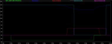
I compared different DC detectors with quite interesting results:
The detector I currently have in the schematic has the disadvantage that it is far less sensitive to negative DC than to positive.
The Zero Audio one is based on the one D. Self has in his books but more complicated. I simulated a circuit half in between both. This runs from dual supplies and does show equal sensitivity for positive and negative DC.
I also simulated another one from Selfs book based on a differential pair that runs from dual supplies as well and shows similar behavior. This one I found rather difficult to get running.
It seems that for equal good +/- sensitivity dual supplies are necessary.
However, once the output is fed to the latch circuit, the difference in sensitivity is negligible.
Attached plot compares my current one with the Self like one in case of negative DC of 3V.
Attachments
Sorry but most IC's are not black boxes. There are less optimal IC's out there but we are debating a very sturdy bipolar (not ESD sensitive) IC that delivers for over 30 years at all large manufacturers. We call the IC's that have nasty habits "bad IC's" and the others are the good ones. The people that don't want to loose valuable time mostly will use the good IC's and warn each other for bad IC's in places like here. Manufacturers often don't want a bad reputation and either revise the IC or stop production. I think no one will design a discrete timer while NE555 or PICs are around. Discrete has a reputation but in real life many imperfections exist. Some IC's have legendary status while having known imperfections.
Yes things can break down. An airplane engine can break off and fall exactly on your house (Donnie Darko) When lightning strikes the IC will be defective but so will the loudspeakers, ampifier, TV and the wiring in the house be.
Anyway design the best you can but my advice is to build something and test all possible circumstances like brownouts, blackouts and the latter twice within seconds. It must protect your valuable stuff but it should not deteriorate sound quality at all. If it deteriorates sound quality or has unexpected behaviour at fault conditions it is not a good circuit for the purpose.
Yes things can break down. An airplane engine can break off and fall exactly on your house (Donnie Darko)
When lightning strikes the IC will be defective but so will the loudspeakers, ampifier, TV and the wiring in the house be. Anyway design the best you can but my advice is to build something and test all possible circumstances like brownouts, blackouts and the latter twice within seconds. It must protect your valuable stuff but it should not deteriorate sound quality at all. If it deteriorates sound quality or has unexpected behaviour at fault conditions it is not a good circuit for the purpose.
Last edited:
This is short-sighted and potentially dangerous advice when applied to mains powered equipment that we build to ClassI standards.................It must protect your valuable stuff but it should not influence sound quality.
I think you are reacting in the wrong thread. It is about speaker protection here. Loudspeaker protection are circuits in amplifiers that protect the loudspeakers in all possible failure scenarios like a power stage going bad and putting 40 V DC on the speakers etc. I would not know what is exactly wrong with what I said ?! Maybe you are used to speaker protection circuits that also senses a human being in the vicinity ?? Knowing british safety measures I would not exclude this possibility. Or do you mean that it should protect the loudspeakers but it must influence sound quality? Please explain what you mean.
In the words of the OP. Please note this is a classic example of preamp/source without muting circuit probably combined with a power amplifier without speaker protection circuit. Icing on the cake often are very slow servo circuits. I am in audio quite long and have seen the laughing faces that told me "protection is for pussies". There always came a day of burning voice coils followed by silence, deep sighs and curses. They then converted to true faith, more often they became true protection jihadis seeking for the most sophisticated circuits with PICs, SSR's, MOSFETs, fan control, temp detection and all possible scenarios on a fancy display. From none to the most exaggerated forms of protection is a switch that apparently takes only a few seconds
In the words of the OP. Please note this is a classic example of preamp/source without muting circuit probably combined with a power amplifier without speaker protection circuit. Icing on the cake often are very slow servo circuits. I am in audio quite long and have seen the laughing faces that told me "protection is for pussies". There always came a day of burning voice coils followed by silence, deep sighs and curses. They then converted to true faith, more often they became true protection jihadis seeking for the most sophisticated circuits with PICs, SSR's, MOSFETs, fan control, temp detection and all possible scenarios on a fancy display. From none to the most exaggerated forms of protection is a switch that apparently takes only a few seconds
Foreword:
I once fried a speaker by turning equipment on the wrong order.
As a countermeasure I improvised a circuit to delay speaker connection on power on.
So far so bad.
I like to get rid of the improvised delay circuit and have a real protection circuit instead.
There are a lot of modules available on the market, some even extremely cheap to buy.
I also found lots of circuits.
But none work the way I need them to.
My requirements for a speaker protection circuit:
1. Delayed connection of speaker after power on.
2. Instant speaker disconnection on power off.
3. Quick speaker disconnect in case of DC on amplifier output.
4. Latch relays off when any fault occurred.
5. Can be used for my dual mono design without hard wiring ground of the two amps together.
6. Can be built from parts I have at home or can source easily and cheap.
7. Is component selection invariant.
8. Is supply invariant from 12V to 24V.
9. Can be configured in a lot of ways so that others can make use of it easily.
Last edited:
"circuits with PICs, SSR's, MOSFETs, fan control, temp detection and all possible scenarios on a fancy display. From none to the most exaggerated"
Yes, I am one of those. I started a speaker protection thread about this a few years ago - I fried both the bass units in one of my B&W 703's. A few months later I designed a new amp (e-Amp) and used a MOSFET relay. All my amps use this technique now.
I would not get any more complicated than needed on protection. The uPC chip is great,mouth I worry about fakes.
As long as you disconnect the speakers if you get more than 1 V or thereabouts you are ok. And you don't need to be overly concerned about it being exactly symmetrical - to within a few hundred mV of either side is ok.
Remember, the more complicated it is, the more chance it can go wrong.
Remember, the more complicated it is, the more chance it can go wrong.
My motto in life
Andrew, totally agree with the approach. We use Atmel chips - doesn't matter, the concept is the same.
Just one more detail with regards to the approach, used in "21-st century" board to ensure high reliability - we use two redundant "execution" channels when reacting on DC offset - one channel is purely analog - signal from the offset sensor directly disconnects the the speaker, deactivating the SS speaker relays.
The other signal initiates a hardware interrupt, making the processor deactivating the same SS speaker relays, then shutting down the amp and indicating the reason of shutting it down (DC offset).
Those 2 deactivators (BJTs) are electrically arranged in series - the one opening earlier will disconnect the speakers (normally, that's the analog one).
In case, by some reason, one of the ways to disconnect the speakers (analog or digital) fails - the other one will do it anyway.
when i will have time i will design with 16-pin AVR speaker protection using Analog-To-Digital conversion for mV detection...LCD readout for digital volume potenciometer and AC-power off on amplifier off....
I found I didn't need an a2d converter on my PIC speaker protection circuit.
If I use a voltage divider into a PIC input pin the PIC pin switches over at 2 volts. I just scale the resistors to match.
I use another pin with the voltage divider to 5 volts to look at the negative phase.
Andrew, totally agree with the approach. We use Atmel chips - doesn't matter, the concept is the same.
Just one more detail with regards to the approach, used in "21-st century" board to ensure high reliability - we use two redundant "execution" channels when reacting on DC offset - one channel is purely analog - signal from the offset sensor directly disconnects the the speaker, deactivating the SS speaker relays.
The other signal initiates a hardware interrupt, making the processor deactivating the same SS speaker relays, then shutting down the amp and indicating the reason of shutting it down (DC offset).
Those 2 deactivators (BJTs) are electrically arranged in series - the one opening earlier will disconnect the speakers (normally, that's the analog one).
In case, by some reason, one of the ways to disconnect the speakers (analog or digital) fails - the other one will do it anyway.
Yes - this is how I did it with my e-Amp board as well!
Regards
Andrew
Ok, I see I get pushed to the uPC1237 solution and I will have a deeper look at it.
vzaichenko:
That's the right attitude!
No compromises on safety critical designs.
Better have redundancy, separate paths, self monitoring everything, huge margins, everything bullet- and idiot-proof. Maybe even rad-hard so you can listen music your last hours after day zero.
Some time ago I worked for a company that had to do with electronics that made people die if it failed (plane falling from sky literally).
This has left some marks on me - for the good and the bad.
So excluding a scenario like "it is unlikely that one output goes negative and the other one the exact amount positive" is just unthinkable for me.
So is buying ICs from some garage guys on ebay from China.
Is the uPC1237 available from a real and reputable distributor? I mean one that has all the quality procedures in place, makes audits, continuous improvement, has an adequate parts storage, packs parts in ESD protected environment only and so on?
You will never find anyone(distributor) actually testing out these parts unless they come straight from the mfg who takes on that responsibility.
We are talking about and old NEC part, UPC1237. NEC is out of the fab business.
BTW, upC1237 is not static sensitive, it is not CMOS.
They shut down a thread in which folks were complaining about utsource, they claimed they do not test anything, you take your chances.
We are talking about and old NEC part, UPC1237. NEC is out of the fab business.
BTW, upC1237 is not static sensitive, it is not CMOS.
They shut down a thread in which folks were complaining about utsource, they claimed they do not test anything, you take your chances.
- Home
- Amplifiers
- Solid State
- Improved speaker protection circuit