Hi jbator,If for RB-976 NFB resistor is 8,25kOhm does it mean that input ground resistior should also be 8,23K instead of 33K used for RA-820?
It's preatty low. Probably will need input capacitor incrase.
Sorry for the late answer - I have had other things to deal with.
The different dc loading (R635 vs. R604)of the LTP will give a bit of output offset (and definitely if the LTP trannies are well matched), but it is normally less than 80mV. Such a dc will only give a standing (0.08V(sq) / 8 ohm) or less than 1mW in the woofer.
The feedback resistor (8k25) determines the gain of the stage with R611 (1 + R635/R611), here x20 or 26dB.
R611 and C605 determines the NFB low -3dB roll-off frequency - here (1 / 6.3x100uFx432) = 3.7Hz. (I normally replace the old 100uF with a new 220uF).
Resistors R602 and R604 reduces gain slightly by R604 / (R602+R604), here x0.96. So, if you reduce R604 to 8k25, you'll have to reduce R602 to get the same ratio. And yes, the input low frequency is determined mainly by C602 and these resistors, so in theory you should increase it from 10uF to 33uF.
Or live with a roll-off of 1.8Hz from the 10uF.
Hope this helps.
Per
RE: External 30V PS only for testing, upgrading, & tweaking Rotel RB-98X amps.Tony, yes that would work fine. Make sure that the dimensions will fit.
Per
I don’t follow the “Make sure that the dimensions will fit.” remark.
I’ll attempt later to post a link to same for clarity’s sake
many thanks. Tony
Ah, now I see you mean bench top lab supplies, I use 30V/3A which works fine. Make sure that they have a good and easily adjustable current limiter feature.RE: External 30V PS only for testing, upgrading, & tweaking Rotel RB-98X amps.
I don’t follow the “Make sure that the dimensions will fit.” remark.
I’ll attempt later to post a link to same for clarity’s sake
many thanks. Tony
Per
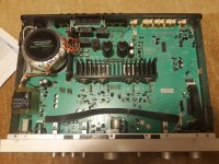
Hi,Hello again. Here are some pictures from my Rotel.
I'm not done with the VAS settings yet. Without 330pf the right channel is not stable.
Pure beauty
") I would like to ask you about the Jantzen caps. I see 1,5 uF.... is this what you could recommend? Have you tried other values? I am planning to replace this electrolytics for an PP and wonder what values to choose. I have Rotel Ra-02.
I would like to ask you about the Jantzen caps. I see 1,5 uF.... is this what you could recommend? Have you tried other values? I am planning to replace this electrolytics for an PP and wonder what values to choose. I have Rotel Ra-02.Hi Guys,
I must admit, that this is a great thread, and I must thank you all. I read it twice. Also I've read those threads (Simple upgrade for Rotel RA-01 amp, Upgrades to a Rotel RA-931 Integrated, and this rotel ra-02 mods) I am non-professional hobbyist, user of the Rotel Ra-02 – I do not use Tone section and Phono section (I play records on made by myself phono tube preamp inspired on EAR834). I have some soldering skills, but lacks of understanding “why it’s like that”. I want to service and clean my Rotel RA-02 and I have some questions. As I mentioned above Tone control and Phono section maybe I just clean and replace the electrolytics.
But since I will remove electrolytics I could do some mods, that I’ve read here about. Simple – cause I can do just simple measurements and I have lacks in understanding. So what I am planning to do:
1. Clean a bit
2. Recapping ale the electrolytics by the same values – currently there are Panasonic FC, I will change it for Nichicon KZ and Elna SIlmic II (those I have)
3. Change “Big Caps”, currently Rubycon 6800 uF/50V and here my first doubt is what to choose. Mundorf 6800uF/63V or ELNA LAO 10000/50V ? Could you recommend something? Rotel Ra-02 is very thin and max height is 45 mm. Mundorf 8200 uF/63V in reality is 47 mm high, not 45 mm as per catalogue.
4. There are 3 electrolytics 10 uF/50V in the signal path and here I’m tempted to do some upgrade. I have Elna Cerafine, however maybe some PP saps would be better idea? C501, C502, C515, C516 – there is not much space, but C601, C602 could be easily replaced by bigger PP cap. In this thread and here I’ve read many ideas like:
a) bypassing C501, C502, C515, C516 with 1nF PP cap
b) removing some of those 3 pairs
c) replacing some of them by PP cap. But no idea what capacity suits the best. I’ve already read about 1uF, 2,2 uF, 3,3 uF, 6,7 uF, 7,5-8,2 uF. Any Idea how to choose it? I know that by ear, but here you have already mentioned WAF (Wife acceptance factor)… No time for constant improvement, small kid at home.
d) I’ve read about DC coupling, that you recommend, but I don’t know how to do that exactly. I play music from many sources, and cannot be sure is some DC will come in.
5. I could change 330p ceramic capacitor (no idea what is VAS) to 220p, what you have mentioned in this thread many times. But to what? Wima PP? what about Silver Mica? In the power amp section there is more ceramic caps, and maybe I could change them to? I could stay with the value, but change for PP or Silver Mica?
6. I was thinking to change some of the resistors for better quality, but I can see that in my Rotel some resistors are already pretty good.
In the amp there is a lot of Polystylene and Mylar capacitors, that I could do the change, but I don’t know if there is sense to do that.
I’ve read also about changing (or removing?) fuses at the end, but not sure about that.
I would appreciate your help,
Good day,
Peter
Attachments
Last edited:
Hi Peter,
Well, replacing the electrolytics is a good idea on a almost 40 years old amp. And your RA-02 will and can give just as many years of listening pleasure if you do. But it is way too easy to go over the top and ”guild the Lily” as we say. A bit like renovating a vintage car where your unbound enthusiasm urges you to polish or chrome that deep-down bolt which nobody will ever see again.
I go for the 'most bang for the buck' stuff as I enjoy listening to music as much as tinkering.
1) Yes, cleaning up is vital to see what you are doing. Rotels are notorious dust collectors. A thin paintbrush and a vacuum cleaner will quickly dust things off. Then, as you remove old components it is easy to use an alcohol wipe on the pcb.
2) I will probably get into hot water with other DIY’ers now, but IMHO theonly major audible difference between different e-caps make and models are the way that they distort.
In the signal path I try to always use film caps – or where possible - no caps. (If you do have to use e-caps for ac signal coupling, use Non-Polarised (NP) types).
In DC duty (decoupling and stabilising, etc.) you of course need the high uF e-caps, and I think highly of the Panasonic FM series. They are excellent quality, more resilient (105°C types) and have a superb low internal resistance (ESR). And they fit nicely and non-vibrating onto the places on the Rotel pcb.
3) Mundorfs are indeed excellent caps, but I have some difficulties in justifying the price vs. quality balance. For the RA-02’s I found that Cornell-Dubilier 10,000uF 50V (30mm x40mm) makes a very good cap that you can exactly shoehorn in place of the old Rubicons. Other modern cap types (EPCOS, etc.) are actually not bad either, but as you said - size does matter in the RA-02.
4) The fewer caps in the signal path the better, but you always need a cap in front of the preamp as you’ll never know if a source has some DC on it. For the two C501/502 I use the red WIMA 3.3uF MKS2, again as with the FM’s because of their quality and reliability. I have never had a single one of those out of spec or failing. And the WIMA fits straight in place.
Yes, the MKS2 is a PE type, but in double blind listening tests I have always found it very difficult to actually hear much difference between PE and PP/PS/etc. film caps.
(Again – I can already hear the gasps of incredulity from people with more honed ears than mine – but at least I am being honest about my hearing limit of 20kHz). Above that frequency I merely enjoy my Tinnitus.😇
You will note that 3.3uF is smaller than the original 10uF. The value determines the low frequency cut-off with R503/504 according to F(-3dB) = 1 / 2*pi*RC so you will have increased the low end from 0.16Hz to 0.48Hz. You can get 4.7uF or even 10uF MKS2's, but the cost and size goes up for little gain, as the main 3.4Hz low end cut lies later in the NFB’s R611/C605.
......I think I will pause for now – this post is probably already getting too long. I will soon be upgrading a RA-02 from scratch and could show you in detail what I do and why.
Per
Well, replacing the electrolytics is a good idea on a almost 40 years old amp. And your RA-02 will and can give just as many years of listening pleasure if you do. But it is way too easy to go over the top and ”guild the Lily” as we say. A bit like renovating a vintage car where your unbound enthusiasm urges you to polish or chrome that deep-down bolt which nobody will ever see again.
I go for the 'most bang for the buck' stuff as I enjoy listening to music as much as tinkering.
1) Yes, cleaning up is vital to see what you are doing. Rotels are notorious dust collectors. A thin paintbrush and a vacuum cleaner will quickly dust things off. Then, as you remove old components it is easy to use an alcohol wipe on the pcb.
2) I will probably get into hot water with other DIY’ers now, but IMHO the
In the signal path I try to always use film caps – or where possible - no caps. (If you do have to use e-caps for ac signal coupling, use Non-Polarised (NP) types).
In DC duty (decoupling and stabilising, etc.) you of course need the high uF e-caps, and I think highly of the Panasonic FM series. They are excellent quality, more resilient (105°C types) and have a superb low internal resistance (ESR). And they fit nicely and non-vibrating onto the places on the Rotel pcb.
3) Mundorfs are indeed excellent caps, but I have some difficulties in justifying the price vs. quality balance. For the RA-02’s I found that Cornell-Dubilier 10,000uF 50V (30mm x40mm) makes a very good cap that you can exactly shoehorn in place of the old Rubicons. Other modern cap types (EPCOS, etc.) are actually not bad either, but as you said - size does matter in the RA-02.
4) The fewer caps in the signal path the better, but you always need a cap in front of the preamp as you’ll never know if a source has some DC on it. For the two C501/502 I use the red WIMA 3.3uF MKS2, again as with the FM’s because of their quality and reliability. I have never had a single one of those out of spec or failing. And the WIMA fits straight in place.
Yes, the MKS2 is a PE type, but in double blind listening tests I have always found it very difficult to actually hear much difference between PE and PP/PS/etc. film caps.
(Again – I can already hear the gasps of incredulity from people with more honed ears than mine – but at least I am being honest about my hearing limit of 20kHz). Above that frequency I merely enjoy my Tinnitus.😇
You will note that 3.3uF is smaller than the original 10uF. The value determines the low frequency cut-off with R503/504 according to F(-3dB) = 1 / 2*pi*RC so you will have increased the low end from 0.16Hz to 0.48Hz. You can get 4.7uF or even 10uF MKS2's, but the cost and size goes up for little gain, as the main 3.4Hz low end cut lies later in the NFB’s R611/C605.
......I think I will pause for now – this post is probably already getting too long. I will soon be upgrading a RA-02 from scratch and could show you in detail what I do and why.
Per
Good morning,
That's great news, so I will learn something. Thank you for the maths explaining to capacity of the PP caps and influence on LF.
Actually I am reading this thread for the third time - once with understanding will be enough, I guess
In one week I will have knee surgery and I will start my work in about 2 weeks. But I have no osciloscope just multimeter and ear. Have a nice day
Ps. Your post was far from "too long"
Peter
Hi Per, good morning.
When do you plan to start the RA-02 upgrade? I am already after surgery and I think I'll start next week. To my previous list od mods I will add
7. Increase C605, C606 to 220 uF from 100 uF - this mod I have also read in this thread
And I already bought Mundorfs, cause I couldn't get anything else here in Poland. CDE was unavailable, only from the US and with shipments costs was even more expensive than Mundorf.
Hi Peter,
Great to hear that you are through the operation and recovering.
The increase from 100uF to 220uF is a good idea, get a quality cap (NP if you can) that fits the place on the pcb to ensure that it sits flush and vibration-free.
The amp I got in was actually a RA-04, but I think that I got some pictures of a previous RA-02 upgrade which I could use as illustration.
If not, I'll soon get two RA-02's in - but unfortunately not after I have packed everything down and set it up in a new house. Moving is always a bl**dy menace!
So, I am afraid that you'll have to be a bit (read: quite) patient, but you could definitely start with the power supply and cleaning the inside of the amp.
Best,
Per
Hello guys,
I've finished my task and what to say?... it is incredibly better, amazing. Haviung just 2 multimetres I could only check tha balance, regilate BIAS and all the improvement is audible, but not so professional as other people here in this thread. I also didn't measure THD and so on. What I did is:
1. Cleaning
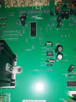
2. Recaping all the electrolytics with the same value, but better quality caps (Mundorf for Power caps, Nichicon Muse, Elna Silmic II, Panasonic FM, etc) and some following changes from the original:
a) there was 3 pairs of signal caps - C501, C502, C515, C516, C601, C602 (extra 2 pairs in Tone regulation section) and I remove first 2 (i put wire jumper) and in the last signal caps I replace electrolytic with MPK capacitor. I put there 6.8 uF but didn't hear any difference when there was 3,3 uF. I tested many variations, and this suits me the best.
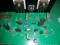
b) In power amp section there was 2 pairs of ceramic capactor C607, C608 (330 pF), C609, C610 (150 pF). At the end I put there Silver Mica Caps, but I also tested WIMA FKP caps. SIlver MIca suits me better. Sound was kind of "lighter". As it was mentioned in this thread, I checked different value for C607, C608 and in the end I put there 220 pF instead of 330. Was much better, however 150 pf was for me worse. I find 220 pF optimal.
c) Increase capacity of C605, C606 to 220 uF from 100 uF
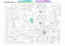
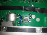
d) I tried to change input resistors to Vishay Dale and XIcon Carbon composite and the difference was audible a lot. It was big improvement, so I was encouraged and change some resitors with the same value, but better quality. I did it with some. See in scheme.
In the scheme I highlight with the blue color when I did some replacement for better quality. With green color I've marked when I did some changes from the original.
The sound now is even hard to compare with the previous sound. If I would have more skills and time I would definetely try changes that AngelP and others is mentioning in this thread. I definetely encourage everybody to do this tunning, cause the difference is incedible.
All the best, Peter!
I've finished my task and what to say?... it is incredibly better, amazing. Haviung just 2 multimetres I could only check tha balance, regilate BIAS and all the improvement is audible, but not so professional as other people here in this thread. I also didn't measure THD and so on. What I did is:
1. Cleaning
2. Recaping all the electrolytics with the same value, but better quality caps (Mundorf for Power caps, Nichicon Muse, Elna Silmic II, Panasonic FM, etc) and some following changes from the original:
a) there was 3 pairs of signal caps - C501, C502, C515, C516, C601, C602 (extra 2 pairs in Tone regulation section) and I remove first 2 (i put wire jumper) and in the last signal caps I replace electrolytic with MPK capacitor. I put there 6.8 uF but didn't hear any difference when there was 3,3 uF. I tested many variations, and this suits me the best.
b) In power amp section there was 2 pairs of ceramic capactor C607, C608 (330 pF), C609, C610 (150 pF). At the end I put there Silver Mica Caps, but I also tested WIMA FKP caps. SIlver MIca suits me better. Sound was kind of "lighter". As it was mentioned in this thread, I checked different value for C607, C608 and in the end I put there 220 pF instead of 330. Was much better, however 150 pf was for me worse. I find 220 pF optimal.
c) Increase capacity of C605, C606 to 220 uF from 100 uF
d) I tried to change input resistors to Vishay Dale and XIcon Carbon composite and the difference was audible a lot. It was big improvement, so I was encouraged and change some resitors with the same value, but better quality. I did it with some. See in scheme.
In the scheme I highlight with the blue color when I did some replacement for better quality. With green color I've marked when I did some changes from the original.
The sound now is even hard to compare with the previous sound. If I would have more skills and time I would definetely try changes that AngelP and others is mentioning in this thread. I definetely encourage everybody to do this tunning, cause the difference is incedible.
All the best, Peter!
Attachments
-
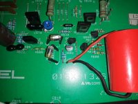
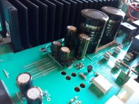 1. Main power caps.jpg343.3 KB · Views: 223
 -
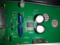 2. 2nd OPAMP 2604PA, signal caps (4).jpg224.2 KB · Views: 162
 -
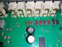 5. Input resistors.jpg352 KB · Views: 169
 -
 7. Power amplifier, last signal caps (1).jpg349.8 KB · Views: 175
 -
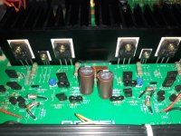 7. Power amplifier, last signal caps (5).jpg362.3 KB · Views: 206
 -
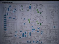 9. Rotel RA-02 schematic with changes.jpg432.4 KB · Views: 207
Thanks for the information. Trying to drop the other forum account but it's still me.The feedback resistor (8k25) determines the gain of the stage with R611 (1 + R635/R611), here x20 or 26dB.
R611 and C605 determines the NFB low -3dB roll-off frequency - here (1 / 6.3x100uFx432) = 3.7Hz. (I normally replace the old 100uF with a new 220uF).
Resistors R602 and R604 reduces gain slightly by R604 / (R602+R604), here x0.96. So, if you reduce R604 to 8k25, you'll have to reduce R602 to get the same ratio
I'm slowly gathering materials for starting work on amp.
Still looks like I'm missing how this value R604 should be picked up. Thought that it should be same as NFB resistor but from your description on Rotel 820 changes I see value more then 2x larger.
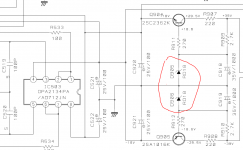
R603/04 - replace with 19k6 MF (Maintains stage gain while matching both LTP input transistor base loading to 8k2).
So what is rule to calculate this base loading?
You are right that the values of each LTP base dc loads should be equal to get a zero (or close) output dc offset if the LTP transistors are well hFE matched.
So, the 'effective' value of R603/4 should be 8k25 as the NFB resistor.
And it is (almost) that because of the direct dc coupling between the preamp and the power stage. R603/4 now sits parallel in a network consisting of R601/2 (681R) and the 22k/33k dividers by the tone switch and into the virtual ground output of the OPA2134. It takes a bit of calculations, but it all works out close to an 8-9k 'effective' value.
Hope this helps, if not I can redraw that part of the schematic to illustrate if needed.
Ok so in case of RB-976 MK2, if I'm keeping DC decoupling C501 in place I have only R503 to ground then. So it should be 8,2K?And it is (almost) that because of the direct dc coupling between the preamp and the power stage
Well, yes if you want the offset to be close to zero (requires well matched 2SA1016's, which the stock ones are probably not). What is the output offset now - less than 50mV?
If you do decide to change R503 to 8k2 the trade-off is that the -3dB low end roll-off will increase from 0.6Hz to 2Hz - unless you increase C501.
But really, both these relatively minor imperfections are basically IMHO each perfectly acceptable, I guess it is down to what you think is most important.
Lower is better, as long as the source can drive the input, and the nfb resistor does not thermally modulate its value.
The lower resistances have lower noise, and less Miller effect interaction.
Typical amplifier input impedance is 10k, so the 8.2k for DC balance R503 would be ok, if your source can drive it.
There would be a slight loss of gain, but not significant. The 10uF input HP filter value should still be ok.
Last edited:
What I want to achieve it's actually valid question. But as for hobby projects not exactly easy to answer.Well, yes if you want the offset to be close to zero (requires well matched 2SA1016's, which the stock ones are probably not). What is the output offset now - less than 50mV?
1. So for start I want to "refresh" the amp so it would work for next few years. I've heard that polystyrene capacitors that this amp is filled with, have high failure rate. They are first to go as some of them are already really steamy/black/blurred inside. Electrolytic caps will not mind for replacement too. But maybe for now I'll keep main caps as they seem to keeps specs.
2. As for offset it's around 12mV so pretty decent. Because I'm running active system with no crossovers, just bare drivers, it will not harm to make it even lower.
Each channel has four of 2SA1016 so x6 it's 24 items. If I will not be able to get decent pairs out of those I will use KSA992.
3. Next is PSRR and generally noise. As those are effective speakers (peak is 109db/W from HF200 driver) I hear slight noise with ear close to the horn.
4. At the end dealing with this THD, VAS loading, sound signature is fun part that I will for sure take.
Any way thank you all for those tips. This thread is fun. Lately I also took reading on Douglas Self book where I'm looking for other clues for this.
Helo friends, I have another question. I see that most (if not all) of this Rotel amps has 18V in circuit for OPAMPS. There are Zener diodes that implicates this. Could you tell me, if there will bo no harm if I change this diodes for 16V or 15V. Becuase if yes, I could try with MUSES Opamps what I would like to try. Many thanks for advise, Peter
Attachments
- Home
- Amplifiers
- Solid State
- Improve a Rotel amp THD by 20dB!