Actually no, my plan is to connect an Audio-GD R1 DAC with an Electrocompaniet AW60 FTT power amplifier via only the volume control referred to in this topic, the first almost certainly with DC output stages and the second totally coupled in D, and I must say that this total DC coupling terrifies me a bit, all that remains is to try and at most put only two nice high quality capacitors in series per channel before entering the final.So after that long winded post, I realized you're likely using tube stages?
Not only that, my idea is also to insert an input selector to fit a dual rack unbalanced phono pre-amp yet to be boxed such as the Pass Pearl 2, so the selector and volume would go inside the same box as the phono pre-amp shielded towards the ground, so I hope in a good reduction of interference pickup. So the scheme I have in mind is this:
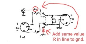
In any case, to return to the initial theme of the topic, I want to try to throw out this reasoning there, to be applied among the following summary diagrams, only to types A and B because C (my favorite) is implicitly immune to problems of imbalance between the two poles of the same channel:
For the first two schemes, assuming an unbalance between the two poles of 12%, if the + pole enters the amplifier with a level of say +850 mV and the - pole instead with a level of -750 (rather than -850), when the input stage inverts the pole - and adds it to the other one, it will obtain 850+750 = +1,600 mV instead of +1,700 mV, but the shape of the wave should not undergo variations because the unbalance should follow a linear proportion function , so at most there will be a slight reduction in volume but there should be no alterations in the wave shape and distortions, which was my real concern.
As regards CMRR (which in the meantime I have studied a little about), it is true that in schemes B and C the disturbances do not undergo any attenuation and pass through unchanged without any mass coming into play but it should not be the task of the input stage of the amplifier eliminate them, as if there were no volume control stage in between? Indeed, still in my ignorance, I can hypothesize that in scheme A, any unbalances between poles due to inaccuracy of the potentiometer could lead to harmful unbalances of the disturbances between the two poles, and in that case the input stage of the amplifier, seeing them different, it would make them move forward. It is true that for short connections we are talking about little things that are certainly not very influential but it is the principle that interests us. In other words, I think it's a good idea to ensure that the disturbances themselves have as little influence as possible from the volume control, which is why I'd avoid scheme A, but I'm here precisely because I'm inexperienced and looking for comparison.I'd personally choose the simple 4-gang pot standard attenuator circuit, placed near the receiving end. The mismatch in output impedance (from the above value tolerance) and the pos/neg path attenuation mismatch will not be a deal breaker. A proper balanced input is immune to this anyway.
@andreaemme Add the same value R to gnd as inline with single ended input. This will balance impedance better and may improve CM noise a little.
Option C is best for several reasons, as you already know. Its self balancing and more precise than other options. A is used more commonly for compatability issues, and most people wouldn't care about any potential depending on input topology on receiving end. Parasound uses it on their A series amps, as many other pro-sumer stuff.
Another great (but more expensive) scheme using option C is adding an isolation transformer. This eliminates the need for coupling caps, quiets down any pot wiper noise (depending on where exactly its inserted) and how well the compensation is executed.
Attachments
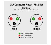
If I understand correctly, you're attempting to read the pin numbers on the XLR connectors?ahkk this is impossible to decipher...there's no pin numbers on the xlr's...and there seems a disregard for what should be balanced operation...
You can identify this with a multi meter set to ohms.
In 99.99% of cases, XLR shield ground is designated as pin #1.
That leaves pin #2 = signal pos(+) and pin #3 = signal neg(-).
This is the industry standard pinout for balanced audio XLR connections.
Attachments

Thank you very much for your precious contribution!Option C is best for several reasons, as you already know. Its self balancing and more precise than other options. A is used more commonly for compatability issues, and most people wouldn't care about any potential depending on input topology on receiving end. Parasound uses it on their A series amps, as many other pro-sumer stuff.
Another great (but more expensive) scheme using option C is adding an isolation transformer. This eliminates the need for coupling caps, quiets down any pot wiper noise (depending on where exactly its inserted) and how well the compensation is executed.
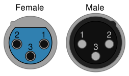
That's a goofy looking XLR layout pic since it shows the pins 120 degrees apart.This is the industry standard pinout for balanced audio XLR connections.
Here's a much better one:
Dave.
Attachments
Opss..I wrote bad, obviously I intended to write: "In a 'classic' unbalanced interface I learned to use a potentiometer with a resistor possibly > 10x source output impedance and < 1/10x amplifier input impedance.", my apologies for my error.In a 'classic' unbalanced interface I learned to use a potentiometer with a resistor possibly > 10x source output impedance and < 10x amplifier input impedance.
yeah i know the industry standard for xlr pinouts, problem for me is that andreaemme seems to be using pin 3 for grounds and attaching signals across pin1 and 2.
maybe because i've diagrammed so many xlr pinouts that their respective positions are ingrained to me (not to mention that unless one is careful about connector genders that pins 1 and 2 are often reversed due to their placement)
maybe because i've diagrammed so many xlr pinouts that their respective positions are ingrained to me (not to mention that unless one is careful about connector genders that pins 1 and 2 are often reversed due to their placement)
Please advise what value of quad potentiometer should I use on the balanced output of the Musician Pegasus r2r dac. The output resistance of the analog sockets is relatively high, 1250Ω balanced. Then comes the balanced diy FrontEnd 2022. Thanks.Opss..I wrote bad, obviously I intended to write: "In a 'classic' unbalanced interface I learned to use a potentiometer with a resistor possibly > 10x source output impedance and < 1/10x amplifier input impedance.", my apologies for my error.
- Home
- Source & Line
- Analog Line Level
- Importance of precision in volume control of a balanced signal