Hello everyone, I ask for clarification regarding the best type of potentiometer to create a volume control in a balanced line.
My doubt is above all about the degree of precision of the component, in my ignorance I imagine that while for an unbalanced line a slight misalignment in the resistance values of a stereo potentiometer does not have an appreciable influence on the signal (at most it will suffer a slight variation in level between the two channels), I fear that for a balanced line a slight misalignment between the resistive values of the two + and - poles of the same channel could negatively influence the correct reconstruction of the wave inside the amplifier, but I hope I'm wrong.
Is it therefore possible to use a normal 4-way potentiometer with 10-20% tolerance for a balanced stereo signal or is a high precision component required?
Thank you all.
Channel ("+","-") is not that big a deal. Sony built a whole line of broadcast
VTRs that (BVW-6x/7x ) had a math error in the output line drivers resulting in a 20%
imbalance. Nobody noticed and I only found it by accident.
You have several options.
1: Handle it ALL balanced using stepped attenuators.
2: Handle it all balanced with gain chips like PGA2310/2311.
3: Convert to unbalanced, control gain any method then back to balanced.
G²
For the LEVEL control of my Audio Research SP3A1, I replaced the imbalanced dual gang LOG pot with a KHOZMO 2x100K precision attenuator : it is a 48-position stereo potentiometer using 0.1% resistor SMD set :
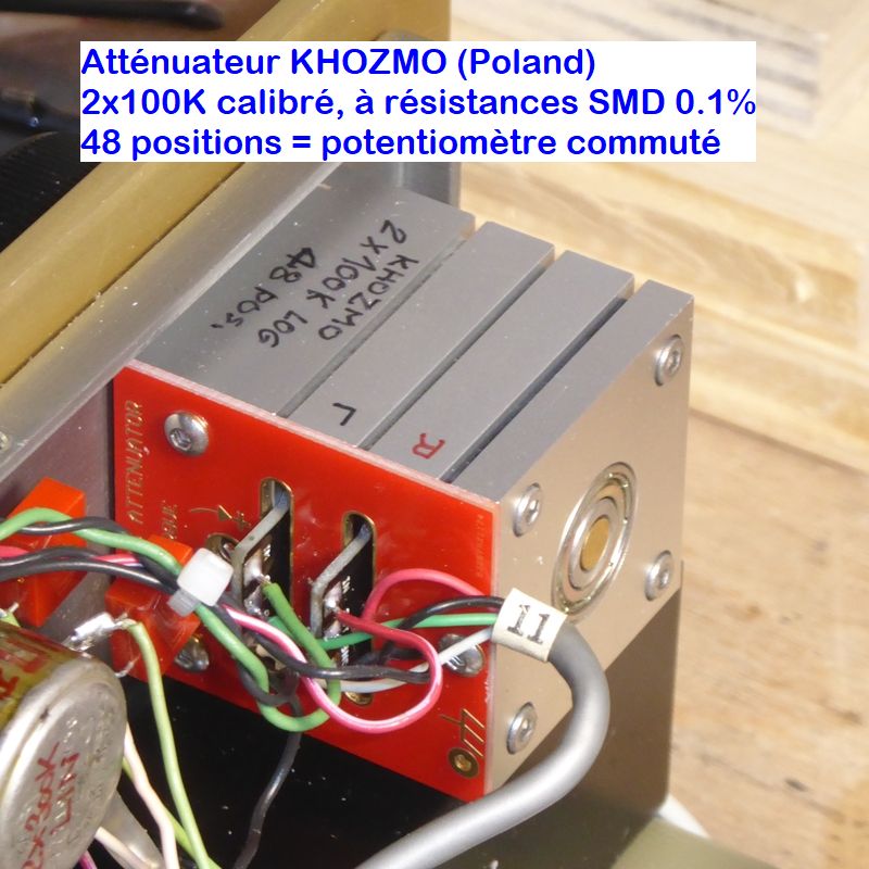
I think that this product exists also in four gang version, with values ranging from 1K to 100K IAAC.
T
I think that this product exists also in four gang version, with values ranging from 1K to 100K IAAC.
T

Thank you, but I reply this: if precision in resistive values matching among poles of balanced line in not so important, why can't be used 'normal' potentiometers to control volume of those, and you suggest to use stepped attenuators?You have several options.
1: Handle it ALL balanced using stepped attenuators.
More: what kind of attenuator is the best for this application: series or ladder (I don't understand shunt type)?
What's the type you used for your application, series, ladder or shunt?For the LEVEL control of my Audio Research SP3A1, I replaced the imbalanced dual gang LOG pot with a KHOZMO 2x100K precision attenuator : it is a 48-position stereo potentiometer using 0.1% resistor SMD set :
The only alternative to Khozmo I've found with SMD resistors at 0.1% tolerance is the Allo 24 step attenuator, really cheaper, but it seems to be out of stock / discontinued. Do you know any other similar products with 0.1% precision?
4. Make a circuit that suppresses common-mode signals, then pass it through a four-channel potmeter, then suppress common-mode again if you are a perfectionist.You have several options.
1: Handle it ALL balanced using stepped attenuators.
2: Handle it all balanced with gain chips like PGA2310/2311.
3: Convert to unbalanced, control gain any method then back to balanced.
G²
Are we writing about a gain control at an input that has to suppress common-mode interference well?
Common-.mode interference are out of my knowledge, I'm writing about just a volume control to put between a high voltage output DAC and a low voltage input power amp using balanced line, and I'm asking if for this is necessary or not a high precision gear or it can be used a quad normal 10-20% tolerance potentiometer, since I think/fear that the two poles of a balanced line should be treated exactly in the same way, or it's not so necessary.Are we writing about a gain control at an input that has to suppress common-mode interference well?
FYI https://www.audiophonics.fr/fr/modu...-encodeur-afficheur-telecommande-p-18344.htmlHello everyone, I ask for clarification regarding the best type of potentiometer to create a volume control in a balanced line.
My doubt is above all about the degree of precision of the component, in my ignorance I imagine that while for an unbalanced line a slight misalignment in the resistance values of a stereo potentiometer does not have an appreciable influence on the signal (at most it will suffer a slight variation in level between the two channels), I fear that for a balanced line a slight misalignment between the resistive values of the two + and - poles of the same channel could negatively influence the correct reconstruction of the wave inside the amplifier, but I hope I'm wrong.
Is it therefore possible to use a normal 4-way potentiometer with 10-20% tolerance for a balanced stereo signal or is a high precision component required?
Thank you all.
Common-.mode interference are out of my knowledge,
I think/fear that the two poles of a balanced line should be treated exactly in the same way, or it's not so necessary.
That depends on how much common-mode suppression you need... If the distance between the DAC and the amplifier is not exceedingly long and if there are no ground loops, some imbalance will probably do no harm.
I prefer floating balanced shunt to ground attenuation topology. With this you only need one resistive element between pos/neg drive to attenuate, using only one dual deck pot/attenuator for 2 channels. Linear attenuator elements are far more precise at any given level than log elements, but it compromises range.
It really depends on your ability to hear comparative differences in level to tell how much imbalance is acceptable. Most people can't pick up less than 15%, but speaking for myself, I can pick up on 5% imbalance with a mono source. For stereo, you'd be very hard pressed to hear less than 10%.
I usually select my components to be under 2% within one channel and 5% between channels. The 2% at least guarantees low offset and input bias.
Likely the best resistive attenuator available, especially considering cost and complexity to manufacture. You don't see many attenuators with double ball bearing, not that it does anything for sound. Its just a nice attention to detail. There is this satisfaction in looking at the beauty of a precision piece of engineering.For the LEVEL control of my Audio Research SP3A1, I replaced the imbalanced dual gang LOG pot with a KHOZMO 2x100K precision attenuator : it is a 48-position stereo potentiometer using 0.1% resistor SMD set :
I think that this product exists also in four gang version, with values ranging from 1K to 100K IAAC.
T
What's the type you used for your application, series, ladder or shunt?
@andreaemme :
I used the series type, which works and is connected like a classic potentiometer, like the original one. I had to correct some coupling caps values since the original pot was 2xA500K and KHOZMO do not issue over 2x100K. I took my inspiration from the SP3C schematic, which is the modern Reissue of the SP3A1 form 1999, where the LEVEL pot is 2xA100K.
The only alternative to Khozmo I've found with SMD resistors at 0.1% tolerance is the Allo 24 step attenuator, really cheaper, but it seems to be out of stock / discontinued. Do you know any other similar products with 0.1% precision?
I saw them too - and some equivalents - but I discarded them because they were only 24 step, while the KHOZMO is a 48 steps unit, and... Yes, much more costy !
Likely the best resistive attenuator available, especially considering cost and complexity to manufacture. You don't see many attenuators with double ball bearing, not that it does anything for sound. Its just a nice attention to detail. There is this satisfaction in looking at the beauty of a precision piece of engineering.
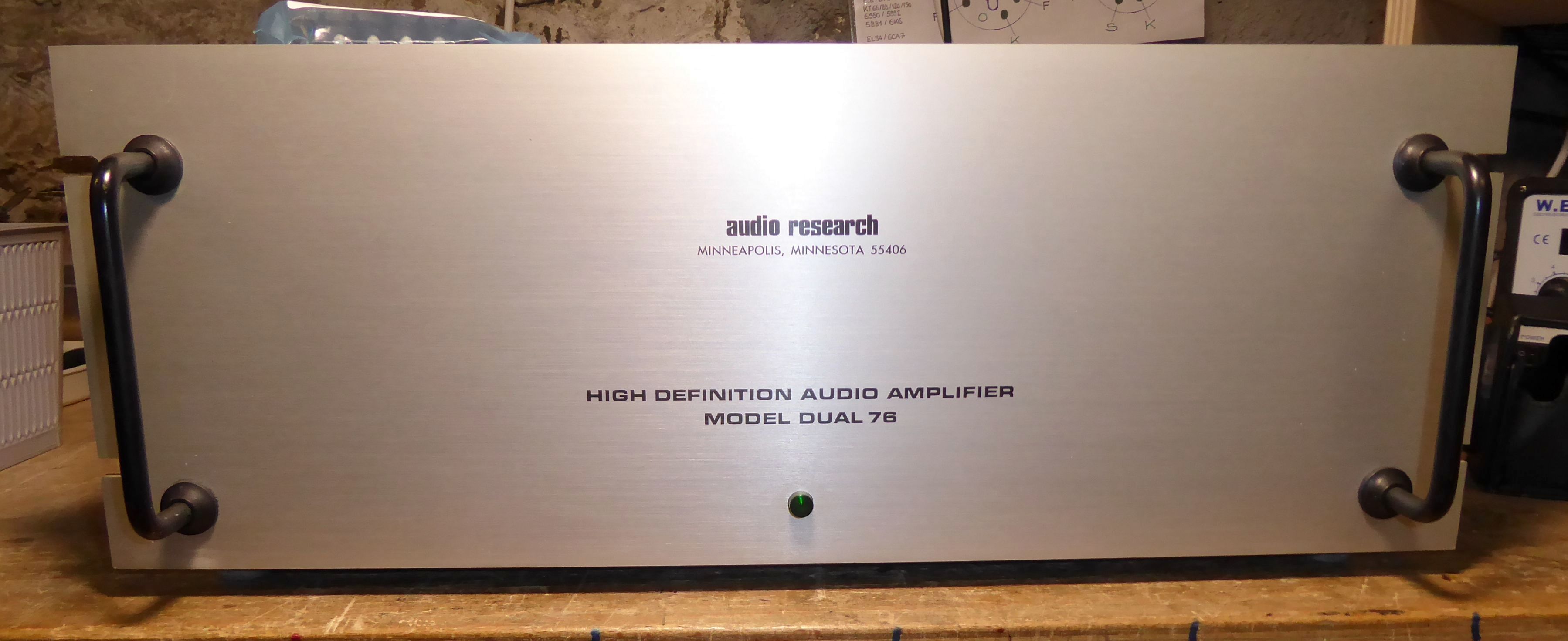
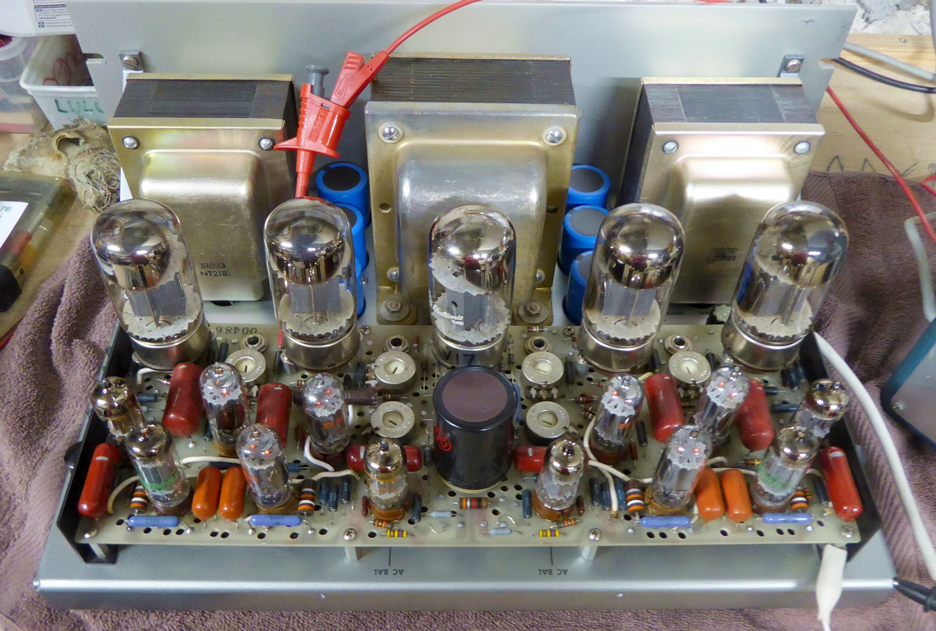
That's it, exactly, @profiguy... Plus add that the KHOZMO offers a 48 step attenuation of premium progressivity and L-R pairing, which is important when the driven amplifier is a matching ARC D76 and its 2x75WRMS output power.
T
If I don't go wrong you are talking about this type of scheme:I prefer floating balanced shunt to ground attenuation topology. With this you only need one resistive element between pos/neg drive to attenuate, using only one dual deck pot/attenuator for 2 channels. Linear attenuator elements are far more precise at any given level than log elements, but it compromises range.
Simple, elegant, it does not require precision at the potentiometer level at least in relation to the prevention of unbalance between the two poles of the same channel, if anything precision is enough for the two input resistors only, the only disadvantage is that it has a minimum attenuation factor different from zero .
I'd like to know how to calculate it, I'll try this way.
In a 'classic' unbalanced interface I learned to use a potentiometer with a resistor possibly > 10x source output impedance and < 10x amplifier input impedance. Therefore, given a DAC with an output impedance of 10 ohm and an amplifier with an input impedance of 330 Kohm, I would use a 33 Kohm potentiometer. In the balanced scheme you proposed I would use a fixed input resistance of 100 ohm and a variable one of 33 Kohm, so that the minimum attenuation still remains very low. Do you think this could be a correct calculation criterion?
I've found this alternative type too:
but return into play the precision factor for the two potentiometer lines of the two poles of the same channel, assuming that it could be a real problem,
Last edited:
The critical thing to know is that your in line resistance before the shunt becomes the dominant source impedance (including the gain stage output impedance, which would be minimal in comparison considering typical amount of NFB used).
The other thing is the actual application of the attenuator ie. whether its a dedicated volume control or an actual semi-fixed attenuator. This is important because of DC offset or input bias passing through the wiper contact, causing noise every time you touch the setting.
If you settle on actual attenuator circuit values for levels, you'll need to verify whether you have any overshoot or ringing at extreme attenuator settings. You'll be checking up to 100 kHz for even response. This guarantees stability and interconnect compatibility, factoring in wire capacitance and parasitic induction. Sometimes things look great when they're isolated, but as soon as you connect it all together, all havoc breaks loose. I'm likely exaggerating a little, but you can't be too safe with DC coupled gain stages. Sometimes you have to add series resistance to the outputs just to guarantee stability at full bandwidth at all gain setting scenarios. Most of the time, 33 - 100 ohms in series on each leg is enough and won't affect performance, unless of course your picky about resistor brands and types. I'm a Holco fan myself, but its really not that critical in this application IMO compared to NFB resistors in power amps - thats one area where cheap plated steel wire leaded resistors will stick out like a sore thumb.
Its just good practice to avoid using ferrous wire leaded resistors in the signal path. The plated magnetic steel leads can have a bunch of stray inductance, which can hurt SQ, especially in stages with larger voltage swings. Same goes for any coupling caps, but most better film caps usually have tin plated copper leads at a minimum.
Regarding output stability, many poorly designed op amp stages don't use enough or incorrect output compensation. In the event of a stability issue (overshoot, which leads to oscillation in extreme cases) you'll want to have peace of mind your tweeters aren't going to melt down.
The lower end of the FR isn't immune from this sort of thing either regarding input bias swings causing your LF drivers to do bad things if they're coupled directly to the output stages. Extremely large coupling caps can be an issue if they have too much leakage. As long as you aim for low end -3 dB limit of around 5 hz, phase will be flat down to 20 hz, which won't be audible. I've heard many designers claim you can't hear 5 hz, which really isn't the point here. You just don't want a noticeable phase shift in any area of the audible bandwidth, mainly because the - 3 dB cutoff point will have at least 45 degrees phase error, so you can understand that you're only dealing with a few degrees phase error at 20 hz if the -3 dB point has a whopping min of 45 degrees (depending on the total rolloff slope of the output stage).
If you use pure DC coupled stages (as I prefer) and insert your volume attenuator, you'll need to use at least a few hundred ohm series resistance on both input and output to somewhat isolate the large percentage of bias currents in both the input and output stages. The other alternative is using capacitor coupling in between stages, but that may be sacrilegious to some purists. Some decent film / foil caps with parallel bleeders on the output will fix all this with minimal signal degradation, but it will never perform as well as a direct coupled circuit.
As far as calculations, the shunt between pos and neg legs gets divided by two for figuring out actual level drop and insertion loss. You can see, there's alot of stuff to consider if you want high end results without any bad surprises.
Last edited:
So after that long winded post, I realized you're likely using tube stages? You won't need to worry about wiper noise having at least one coupling cap in line. Just insert the attenuator after the coupling cap so you have a place to bleed down the cap leakage. For resistors, I'd stick with Holco or Caddock in the signal path. The Alps blue velvet pots are very good and usually track very well.
When dealing with higher voltage swings, carbon resistor elements can add a healthy amount of 2nd order HD, which many find very pleasing. Metal film sounds more clinical. Most of the time, MF elements don't produce enough K2. The Holcos are a good compromise. They have the least amount of metal film glare compared to other resistor types.
When dealing with higher voltage swings, carbon resistor elements can add a healthy amount of 2nd order HD, which many find very pleasing. Metal film sounds more clinical. Most of the time, MF elements don't produce enough K2. The Holcos are a good compromise. They have the least amount of metal film glare compared to other resistor types.
Last edited:
The other thing is the actual application of the attenuator ie. whether its a dedicated volume control or an actual semi-fixed attenuator. This is important because of DC offset or input bias passing through the wiper contact, causing noise every time you touch the setting.
Interesting @profiguy : on my C712 preamp :
I have that kind of slight noise issue when turning the Loudness control, and at a lesser extent with the Bass and Treble controls. I replaced all the 35V electrolytic coupling caps by 50V ones, thinking that some could be leaky : improvement, but no total eradication as I would expect...
That noise is more perceptible if you turn those controls just after the powering on of the preamp, and diminishes afterwards : this made me think that it was a remaining possible leaky coupling cap issue. But where ? I changed all, with the correct value...
Maybe on a say 47µF/50V, there's a remaining leak due to the capacitor technology, even if the cap is new, and this can cause that little noise on sensitive (or poorly designed) circuits ?
T
What kind / brand of caps did you use? I usually recommend the nichicon muse non polars (green cans).
What you're hearing is likely the caps still charging when the control noise is more noticeable. Sometimes it can simply be the design of the circuit too. As long as the voltage ratings are high enough on the replacement caps, there's nothing really else you can do other than modifying the bleed resistors (or installing some to begin with if not so equipped). You could try some metal film 47k - 100k/0.25W resistors across the output terminals to signal ground. That should eliminate most of it.
What you're hearing is likely the caps still charging when the control noise is more noticeable. Sometimes it can simply be the design of the circuit too. As long as the voltage ratings are high enough on the replacement caps, there's nothing really else you can do other than modifying the bleed resistors (or installing some to begin with if not so equipped). You could try some metal film 47k - 100k/0.25W resistors across the output terminals to signal ground. That should eliminate most of it.
What kind / brand of caps did you use? I usually recommend the nichicon muse non polars (green cans).
What you're hearing is likely the caps still charging when the control noise is more noticeable. Sometimes it can simply be the design of the circuit too. As long as the voltage ratings are high enough on the replacement caps, there's nothing really else you can do other than modifying the bleed resistors (or installing some to begin with if not so equipped). You could try some metal film 47k - 100k/0.25W resistors across the output terminals to signal ground. That should eliminate most of it.
I don't remember the brand... I chose 50VDC instead of 35VDC, and the exact same µF polarized capacitors values as the originals... I did not thought one second about those nichicon muse non polars (green cans) you recommend, @profiguy !
Yes indeed, I agree with you about the remaining noise and circuit design... That said, I can plentifully live with that noise issue, as it is way far from dramatic !
But simply think that my unpretentious NAD 114...
... Is PERFECTLY SILENT on all his pots movements, unlike the much more costy and "tradition of excellence" McIntosh C712 ! Il faut tout de même avouer que cela fait désordre ! 🙄 😆
T
The NAD is likely chocked full of coupling caps. That will make the controls dead quiet.
You may also have huge channel-to-channel imbalance. The typical pot total resistance tolerance is +-10% or +-20%.Simple, elegant, it does not require precision at the potentiometer level at least in relation to the prevention of unbalance between the two poles of the same channel, if anything precision is enough for the two input resistors only, the only disadvantage is that it has a minimum attenuation factor different from zero .
Potentiometers are best used in true potentiometric (voltage divider) circuits.
The second circuit is therefore better in this regard but both circuits suffers from common-mode voltages not being attenuated at all.
I'd personally choose the simple 4-gang pot standard attenuator circuit, placed near the receiving end. The mismatch in output impedance (from the above value tolerance) and the pos/neg path attenuation mismatch will not be a deal breaker. A proper balanced input is immune to this anyway.
- Home
- Source & Line
- Analog Line Level
- Importance of precision in volume control of a balanced signal