Re: Mounting cine mags
I'll check. The Cinemag was 4x4 pins, correct?
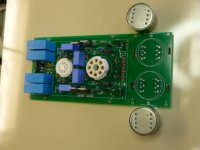
wirewiggler said:It looks like to the cinemags have to be mounted under the board to make pin1 line up. Due to the position of the ground 7 an shield 2&6 I don't think you could mount them on top, correct me if I am wrong.
Thanks
Bill
I'll check. The Cinemag was 4x4 pins, correct?
schematic
It is not possible to get the magazine here in germany.
Can anybody serve me with the article and or schematic,
Thanks,
Reinhard
audiosix@gmx.de
It is not possible to get the magazine here in germany.
Can anybody serve me with the article and or schematic,
Thanks,
Reinhard
audiosix@gmx.de
Pinout
Yes I see that the board pinout is inverse. If you want to mount them on top then you would have to cut a trace or two.
Also one channel has a trace from pin 6 to pin 8, which goes to PCB signal ground , but no trace between 6 and 8 on the other channel, just pin 8 going to signal ground.
Looking at the manufactures info for the CMLI-15/15B pin 7 goes to chassis for the shielding of the case. Pin 6 goes to signal ground on the PCB.
Any comments?
BDP
In the short term I would recommending cutting the incorrect traces -- i think that it's worth re-working the board to correct the error with the transformer and the orientation of the depletion mosfets.
I do this all the time with LM329's -- when I forget whether the view is from the top or bottom. i had thought that the view of the schematic was a projection.
those of you with boards -- point out anything else -- i think that i will make the slots a little bigger and extend the edges through the sides.
An externally hosted image should be here but it was not working when we last tested it.
Jack, do you have any idea if this image is to scale when printed? I want to start putting together a BOM and need to figure out footprints for the various devices.
Thanks!
luvdunhill said:
Jack, do you have any idea if this image is to scale when printed? I want to start putting together a BOM and need to figure out footprints for the various devices.
Thanks!
PM Me and I'll send you the gerber files -- you can use Pentalogix to view them and it will give you the exact dimensions. Everything on the board was from Mouser or DK, save for the tube sox which are from Parts Express.
Jack:
The only difference between the 6DJ8 pinout and the 12AT7 / ECC99 pin out is the later have a heater center tap. On the 6DJ8 this same pin is marked as "IS" on the datasheet, which you are routing to ground. Would it be possible in the next board version to make this connection optional? I'd be interested in running 12.6v heaters for both tubes as well, so it would be nice to support this.
The only difference between the 6DJ8 pinout and the 12AT7 / ECC99 pin out is the later have a heater center tap. On the 6DJ8 this same pin is marked as "IS" on the datasheet, which you are routing to ground. Would it be possible in the next board version to make this connection optional? I'd be interested in running 12.6v heaters for both tubes as well, so it would be nice to support this.
SY:
Is 400V rating sufficient for all the caps? Just trying to get a lower bound on ratings that are safe, to help narrow down a few choices. Seems C5 needs > 350V, but I'm not sure about C3 and C4, as it seem less is okay here, except for possible failure conditions.
Thanks!
Is 400V rating sufficient for all the caps? Just trying to get a lower bound on ratings that are safe, to help narrow down a few choices. Seems C5 needs > 350V, but I'm not sure about C3 and C4, as it seem less is okay here, except for possible failure conditions.
Thanks!
-So, these are the 2 sockets we need?
http://www.parts-express.com/pe/showdetl.cfm?Partnumber=055-502
http://www.parts-express.com/pe/showdetl.cfm?Partnumber=055-514
Tubes:
http://www.parts-express.com/pe/showdetl.cfm?Partnumber=072-845
is this the same as an ECC88?:
http://www.parts-express.com/pe/showdetl.cfm?Partnumber=072-550
Any suggestions of other/better places to get tubes? Thetubestore.com?
- I presume that for a preamp it is better to have the tubes inside the chassis for shielding?
-And for those concerned about the Cinemag PC transformers, I understand that they work fine if mounted under the board?
Mark
Originally posted by Variac -And for those concerned about the Cinemag PC transformers, I understand that they work fine if mounted under the board?
Perhaps if Jack moved two traces, it would be possible to add a 3/8" hole in the center so that the bushing mount transformer could be mounted on the board, then the wires solder in from underneath the board? Seems possible to me ...
Looking at some of the boutique caps, the only ones that really have a chance to fit are Auricaps. The 0.1uF/400V is 0.42'"D x .53"L and the 0.47uF/400V is .60"D x .78"L. Perhaps C5 and C9 could be moved to the right, centered between the DMOS devices and the output caps so these leaded caps could be used (perhaps the holes will need to be enlarged too). Perhaps a a pair of holes could be added as well so a cable tie could secure axial caps. Vcc1/2 and GND test points would have to be moved slightly, but this seems possible. For the outputs, similar holes could be added, but a pair of holes would be used for either leg.
I need the diameter of the pins on the Auricaps as well as the "centers" -- is there an engineering drawing?luvdunhill said:
Perhaps if Jack moved two traces, it would be possible to add a 3/8" hole in the center so that the bushing mount transformer could be mounted on the board, then the wires solder in from underneath the board? Seems possible to me ...
Looking at some of the boutique caps, the only ones that really have a chance to fit are Auricaps. The 0.1uF/400V is 0.42'"D x .53"L and the 0.47uF/400V is .60"D x .78"L. Perhaps C5 and C9 could be moved to the right, centered between the DMOS devices and the output caps so these leaded caps could be used (perhaps the holes will need to be enlarged too). Perhaps a a pair of holes could be added as well so a cable tie could secure axial caps. Vcc1/2 and GND test points would have to be moved slightly, but this seems possible. For the outputs, similar holes could be added, but a pair of holes would be used for either leg.
The hole shouldn't be a problem. I was thinking that a hole in the center of the octal socket with a "key" would be helpful as well.
Going into the city, and tomorrow is "mom-day" so nothing will happen until mid-week.
Thanks Jack! No rush, I'm sure I'll have some other suggestions by then.
One more question for SY. When running this preamp into the F4 dual monoblock configuration, shouldn't R13 and R14 be considered to be in parallel with the input resistors of the F4, for the purposes of calculating the output coupling caps f3 point? I notice Jack changed these to 100K on his build, presumably to "match" the also changed input impedance of the F4. In this case, wouldn't the f3 be around 6.8 Hz (1/(6.28 * 0.47uF * (100K || 100K)) ? Perhaps I'm missing something here...
One more question for SY. When running this preamp into the F4 dual monoblock configuration, shouldn't R13 and R14 be considered to be in parallel with the input resistors of the F4, for the purposes of calculating the output coupling caps f3 point? I notice Jack changed these to 100K on his build, presumably to "match" the also changed input impedance of the F4. In this case, wouldn't the f3 be around 6.8 Hz (1/(6.28 * 0.47uF * (100K || 100K)) ? Perhaps I'm missing something here...
- Home
- Amplifiers
- Pass Labs
- ImPasse Preamplifier