Thanks for the explanation. Hope the in-wall TL works fine, can we see foto's if it's done?
Greetings")
Know this doesn't belong to this thread but as it was requested here, I thought just a short reply wouldn't heart, besides the setup will continue with spherical speakers for my Surround and something similar for the atmos.
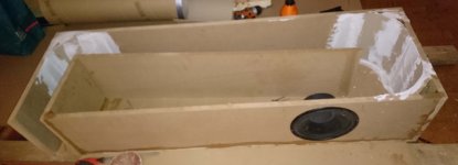
So now its done. The TL sounds better than I hoped for even though it is an old 8 inch quite cheap woofer (Peerless 831858), not bad but it's possible to find better woofers. Since I've got this one already I thought why not. It plays loud enough but it won't move the roof but that was not the purpose. The purpose was to get a good lower end complement. That's exactly what I got, a really great bass response and a clear dry sound - wow! Tuned to 23Hz and is a great complement to the front full range speakers (tuned to 35Hz) for music where it is cut off at 40Hz and it works great for the movie sound where it takes everything lower than 60Hz.
I use an old subwoofer amp from Yamaha that fits perfect for this woofer and the filter stops everything below 15Hz and can play up to 150Hz without any dip in the frquency response.
I still have the center to build (with the same Scan-Speak woofer and tweeter as the front speakers have) and to cover the amplifiers with hatches before I measure the room and fix needed corrections even though the Audyssey MultEQ XT32 does a good job correcting the fr the standing waves must also be tamed. Then I will paint the spherical surround speakers in white gloss and work something out with the atmos speakers. I will go for a 7.2.4 system so four more of the Seas coax mounted in some kind of spherical form and I will complement with another TL later on...
Attachments
That Luxman amp and preamp looks great!
Sounds great to! Maintained and modified.
Baffle Step for Dayton Audio SP-95
Hi, can you pls layout the baffle step circuit for me? Doesn’t each circuit use TWO resistors? Thanks.
Oke, build is as good as done
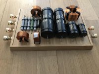
I'm very pleased with the PS-95, I have used these parts for the baffle step.
Resistor
CERAMIC RESISTOR 10 W 3,3 OHM
Coil
SP 0,82 mH / 1,0 mm
Height 18 mm
Diameter 48 mm
Wire diameter 1,0 mm
Internal resistance 0,4 Ohm
Hi, can you pls layout the baffle step circuit for me? Doesn’t each circuit use TWO resistors? Thanks.
A typical BSC circuit is a resistor in parallel with a cap, all this in series with the speaker.
The cap stops high frequencies above a certain point, the resistor determines the amount of BSC.
dave
Thanks, Dave.
The upgrade...
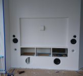
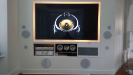
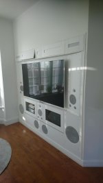
Finally had some time to make some upgrades as earlier stated shouild be done. Builded the center with the Scan-Speak drivers as the mains and experimented with different waveguides for the tweeters and measured the results to be of satisfation for both frequency responce for the 2-4 kHz had some irregular response. For the center where the horisontal spread is important the waveguide is slightly different, more oval for better spread, with a little cost of gain in the frequency response. Together with toing-in the left and right main speaker made the sound better for every listening position and the sound stage was much improved for an all in-wall placed speakers setup. Something I missed with the earlier setup, a huge improvement.
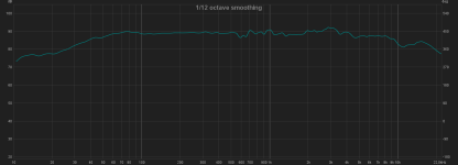
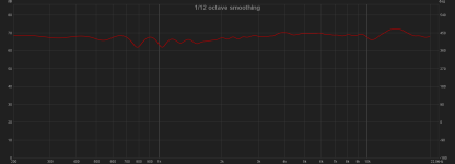
I also made new filters for the main LCR speakers which made more to the sound than I could imagine! Do not cheat on filters is something I have learned after measuring and listening, it is everything! I reduced the annoing bumps in the 700 Hz and 2-4 kHz area I knew was there before, lowered the crossover frequence from 2,8 kHz to 2 kHz for the tweeter to better meet the woofer. Together with a 12dB crossover for the woofer and a 18 dB for the tweeter from earlier 24 dB for both some ringing was decreased. It is like totally new speakers. On purpose i lowered the tweeter output and even if resulted in a non-flat response from 4kHz and up, it is to me a more pleasent listening high frequency response. I now have a flat response +/- 2,3 dB from 16 Hz and up.
The four IKEA made Seas speakers plays so well so these are kept as surround speakers and I put 8" coax in-ceiling speakers for the atmos surround.
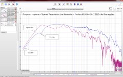
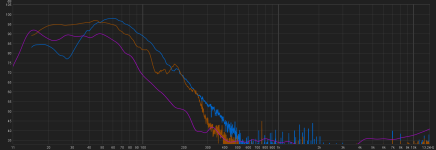
I also replaced the 8" transmission line sub with two 12" transmission line subwoofers. I can really recommend TL as a subwoofer design. I first designed and build a prototype with a 12" Scan-Speak woofer but could not get it to work in a TL design. In my frustration I tested with some old Car subwoofers laying around (since the time I had no need for space in my car trunk) and it showed out to be a perfect match for my TL subwoofer design, can you believe that?! I can say nothing but amazing how good theese sound. The Soundstream GR12 are 4 ohms speakers in serial and driven by a bridged Phonic MAR-4 amplifier which allows enough power to justify any thunders and explosions in movies (do not need any bass shakers at all At the same time it fills the music bottom end real smooth thanks to the TL design.
The frequency response pictures is far-field of the LCR-speakers and the transmission lines (where the purple line is the far-field and the blue is the driver and orange is the port near-field measurements).
Some sealing and painting remains and new silent Noctua fans to withdraw the heat is going to be installed.
Time to start with upgrading the computer with some nice speakers which most likely will be a pair of IKEA bowls bowls with Seas coax drivers which I just like so much. This time I will try to build them with a slave bass driver. That would be intersting to find out how they would sound...maybe even equip it with bluetooth and a battery, that would be nice to bring to the beach!
Finally had some time to make some upgrades as earlier stated shouild be done. Builded the center with the Scan-Speak drivers as the mains and experimented with different waveguides for the tweeters and measured the results to be of satisfation for both frequency responce for the 2-4 kHz had some irregular response. For the center where the horisontal spread is important the waveguide is slightly different, more oval for better spread, with a little cost of gain in the frequency response. Together with toing-in the left and right main speaker made the sound better for every listening position and the sound stage was much improved for an all in-wall placed speakers setup. Something I missed with the earlier setup, a huge improvement.
I also made new filters for the main LCR speakers which made more to the sound than I could imagine! Do not cheat on filters is something I have learned after measuring and listening, it is everything! I reduced the annoing bumps in the 700 Hz and 2-4 kHz area I knew was there before, lowered the crossover frequence from 2,8 kHz to 2 kHz for the tweeter to better meet the woofer. Together with a 12dB crossover for the woofer and a 18 dB for the tweeter from earlier 24 dB for both some ringing was decreased. It is like totally new speakers. On purpose i lowered the tweeter output and even if resulted in a non-flat response from 4kHz and up, it is to me a more pleasent listening high frequency response. I now have a flat response +/- 2,3 dB from 16 Hz and up.
The four IKEA made Seas speakers plays so well so these are kept as surround speakers and I put 8" coax in-ceiling speakers for the atmos surround.
I also replaced the 8" transmission line sub with two 12" transmission line subwoofers. I can really recommend TL as a subwoofer design. I first designed and build a prototype with a 12" Scan-Speak woofer but could not get it to work in a TL design. In my frustration I tested with some old Car subwoofers laying around (since the time I had no need for space in my car trunk) and it showed out to be a perfect match for my TL subwoofer design, can you believe that?! I can say nothing but amazing how good theese sound. The Soundstream GR12 are 4 ohms speakers in serial and driven by a bridged Phonic MAR-4 amplifier which allows enough power to justify any thunders and explosions in movies (do not need any bass shakers at all
At the same time it fills the music bottom end real smooth thanks to the TL design.The frequency response pictures is far-field of the LCR-speakers and the transmission lines (where the purple line is the far-field and the blue is the driver and orange is the port near-field measurements).
Some sealing and painting remains and new silent Noctua fans to withdraw the heat is going to be installed.
Time to start with upgrading the computer with some nice speakers which most likely will be a pair of IKEA bowls bowls with Seas coax drivers which I just like so much. This time I will try to build them with a slave bass driver. That would be intersting to find out how they would sound...maybe even equip it with bluetooth and a battery, that would be nice to bring to the beach!
Attachments
Last edited by a moderator:
diyiggy, I think I can answer that one. When I cut my bowls I used a 1/4" down spiral carbon bit on my router. I also used the smaller circle jig from Jasper. This jig works best for all of my tweeter and smaller woofer cutouts. Finding the center of the bowl, I drilled a 1/8" pilot hole for the center pin to guide the router around the base of the bowl. My first cut is the diameter of the outside flange of my woofer and only to the depth of the woofer flange. I then selected the actual whole cutout for the basket and magnet of woofer. I had made the mistake of not sanding the poly finish off of the outer edge od the 2 bowels where they will glue together. My first attempt fell apart from the glue not setting over the smooth surface of the poly. I hope this helps you out diyiggy!
As Kingfisher described is probably the easiest way how to do it.
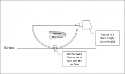
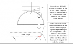
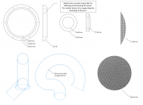
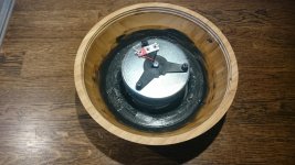
I started to flatten the edge where the two halfs shall be glued together (Picture "flattening the edge") by drilling a center hole and bolted it to the surface (still must be able to rotate it. Then i mounted my router to a jig (I used some wood and attached the router to it in a fixed height and then rotated the bowl. You can of course sand it down as well...
When doing this the two bowls mounted together won't be totally round but it is possible to sand the outside a little wich will make it look round so do not take away more than needed to get a flat surface for the bowls to be glued together.
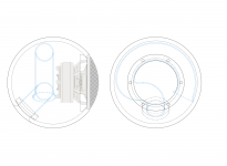
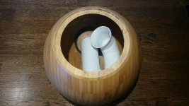
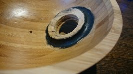
Then I used the router to cut out the driver hole but it is probably easier to use a circular saw as Kingfisher described (picture "Cut the driver hole"). Do not cut deeper than the thickness of the driver's flange height as I tried to show in the picture. I also added a wooden ring inside to stiffen up the area around the hole and also to support the screws for the driver fastening.
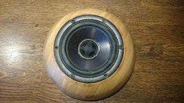
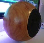
Hopefully this explains how I did and how you can do it. I added some pictures from my speaker for some ideas.
If you have any more questions or want some more info I will of course help you out as much as possible.
I started to flatten the edge where the two halfs shall be glued together (Picture "flattening the edge") by drilling a center hole and bolted it to the surface (still must be able to rotate it. Then i mounted my router to a jig (I used some wood and attached the router to it in a fixed height and then rotated the bowl. You can of course sand it down as well...
When doing this the two bowls mounted together won't be totally round but it is possible to sand the outside a little wich will make it look round so do not take away more than needed to get a flat surface for the bowls to be glued together.
Then I used the router to cut out the driver hole but it is probably easier to use a circular saw as Kingfisher described (picture "Cut the driver hole"). Do not cut deeper than the thickness of the driver's flange height as I tried to show in the picture. I also added a wooden ring inside to stiffen up the area around the hole and also to support the screws for the driver fastening.
Hopefully this explains how I did and how you can do it. I added some pictures from my speaker for some ideas.
If you have any more questions or want some more info I will of course help you out as much as possible.
Attachments
-
 flattening the edge.png12.6 KB · Views: 345
 -
 Cut the driver hole.png26.6 KB · Views: 342
 -
 Overview.png159.6 KB · Views: 344
 -
 Details.png247.3 KB · Views: 338
 -
 DSC_0443.jpg701.4 KB · Views: 323
 -
 DSC_0445.jpg844.8 KB · Views: 230
 -
 DSC_0446.jpg990.2 KB · Views: 227
 -
 DSC_0429.jpg712.1 KB · Views: 231
 -
 IKEA 20 cm Seas Coax.jpg669.4 KB · Views: 235
 -
 Windowed speaker frequency response.png32.1 KB · Views: 242
Last edited:
Thanks…)
An awesome documentation and craftsmanship, very clean job and the loudspeaker is pretty.
Kudos.
Guys the level is climbing more and more, when I think I just have begun a simple little 3 ways classic a la Harbeth as a first diy project, you guys with your ambitious diy are very a motivation source....
An awesome documentation
and craftsmanship, very clean job and the loudspeaker is pretty.Kudos.
Guys the level is climbing more and more, when I think I just have begun a simple little 3 ways classic a la Harbeth as a first diy project, you guys with your ambitious diy are very a motivation source.
...Hi Bohusbusen,
That's really impressive work. I'm a fan of having things hidden so I definitely appreciate it. Would have been nice if LCR didn't need bass ports to cut down on holes. Well done though!
Thank you, I am satisfied to hide the stuff in a wall, even if it makes it impossible to later on change the position of the speakers. I have experimented as much as possible before settled positions but I have restricted area so everything is a matter of compromises. This time it turned out well so I guess I am quite satisfied.
Yepp, I agree that it would be nice with less holes (ports). The background is that I put the speakers in the wall and it earlier had one port facing down but to have the ports facing front I needed to make two smaller since the front area didn't allowed a 3" port. The speakers are designed as ported and the woofer likes it better than closed box. I also wanted them to play lower in frequency when listening to music (tuned to 42 Hz). For movies the cut-off is set to 80 Hz so it does not mais not needed to tune it lowtter but for music the cut-off is set to 60 (and the sub as well) which makes it a smooth transition to the sub.
Really need to fix the ventilation though...it gets hot after a while https://files.diyaudio.com/forums/images/smilies/smile.gif
Thanks...
An awesome documentation
Kudos.
Guys the level is climbing more and more, when I think I just have begun a simple little 3 ways classic a la Harbeth as a first diy project, you guys with your ambitious diy are very a motivation source.
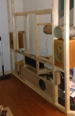
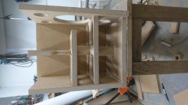
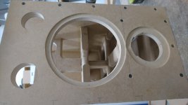
Nice, keep us posted. Dont cheat on the bracing in the box (pic's of my center as an example) which does a lot to the bass according to my experience. Also try to keep the speakers as tight together as possible and don't cheat with the filter components.
Attachments
.....
If you have any more questions or want some more info I will of course help you out as much as possible.
Did you use: L12RE/XFC H1602-04/06 ?
//
Yes it might be so, vertical or horisontal or both. As long as (according to my own opinion) a rigid enclosures sounds better in the lower frequencies. The driver's magnet is in tight contact via a thin rubber between the magnet and the shorter brace, thats why I have horisontal in this case. A small cutout is made allowing the ventilation of hte motor to work properly. I believe there are as many opinions and solutions as there are diy builders and next time might very well have another design. /B
- Home
- Loudspeakers
- Multi-Way
- Ikea spherical speakers, first build done.