I went in with the desire to know the truth. If it lines up with your observations, great.You went into this with a desire to disprove what I've been saying, and that's fine.
If it does not, well then it does not. Given you cannot explain your observations with theory, we ran into a wall a while ago.
No no no... I refuse to do unnecessary work. The results in simulation are convincing (maybe not to you...) and agree with theory. I will not go and waste time measuring stuff unless I know what I am hunting for or trying to prove. What would I be trying to proof, that the simulation is lying to me? I have no reason to believe that. At this point, my hypothesis and technical explanation has been proven by simulation work.You refuse to do the actual work and sit on your behind instead of getting your hands dirty. That's fine too. Just be honest about it.
Now, if you give a solid technical explanation for your observations, and I doesn't agree with the simulator, I will go ahead and build the circuit and do the measurements. If you can't, my story has been proven to my satisfaction (maybe not to yours, but you don't even want to discuss the technical aspect).
Yes, but for verification purposes. Circuits are designed to work on the first shot. An IC mask set costs between $100k and more than $1M depending on the process, do you think management will be happy if you screw up and need to do a second full mask set?Lastly, the one thing designers say is that you can simulate a circuit, but you have to build the think to be sure it works.
Bottomline, simulation works and is really close to reality. LTSpice and Bob models are good too. If you refuse to accept these facts, well, you are out of date.
Finally, as I stated before, ICs are a special case. You didn't read that I guess.
I did say that rules that apply to parts on a single die do not hold to individual parts.
I did read, and I mentioned they are not a special case. Same principles apply. But, I am open minded, tell me what rules don't apply? I am very curious to learn.
FYI, today, devices are encapsulated in SOI and isolation trenches, so thermal coupling is not nearly as good as it used to be. Thermal effects are more close to individual devices. You won't find this in any text book.
I feel you are out to win debates (as I stated earlier) instead of finding out the truth about what is going on. Roll up your sleeves and earn the right to comment as you have. Right now your understanding exists in a make believe world of special circumstances and simulations. Man up and do the actual work Sandro.
To reiterate, I am seeking for truth and its associated theory/explanation. You are trying to convince me by telling me you made observations and measurements, but you don't have an explanation for them. Sorry but that is not going to cut it.
I made a story, which is technically sound, and proved it in simulation. Unless you give a solid reson on why my observations and explanations are wrong (and saying that your measurements don't agree, or the simulator is bad, or models are wrong, is not good enough), OR you back up your observations with a technical explanation, I am not wasting time/resources building the circuit.
Until now, you have tried to convince me that I am wrong with opinions that range from:
You (meaning me) lack a proper education hence you do not know what you are talking about -> The simulator is lying to you and models are wrong -> BJTs don't work like they are supposed to -> ICs do not behave the same as discretes -> My measurements are right hence everything else is wrong, though I cannot explain the underlying root cause.
But you have not provided anything to back any of these opinions. As my old boss used to tell me, opinions are cheap.
At the end of the end of the day you don't want to listen nor discuss. Even if I built the circuit, you are going to say I measured it wrong and that I mangled the experiment in my favor (you already accused me of that). You are too personally attached to this from the hundreds of hours you have spent on it and $1k's of dollars. So admitting you are wrong, would mean you wasted a ton of money and time.
Final words, I will consider building the circuit if you provide a satisfactory explanation on why 'BETA is a strong factor in setting the current ratio between output devices' and why my experiment is wrong. Else, I am staying with my story which to me is the current truth given the sim work I did. I doubt you will given our discussion thus far, but, I may be surprised. That's your challenge.
Best, Sandro
Last edited:
BTW, you keep saying I am being dishonest. Not sure why. I never said I was going to build anything. All I asked was for you to share if you knew the root cause of your observations. At first you said you knew it, and then realized you can't because you don't know it (As you said: Maybe I have the mechanism wrong).
It is not my fault you can't explain what you observe and that every argument you make is not technically sound or rediculously vague. I guess you just don't like being challenged and are not interested in learning hence all you do is say go build the circuit rather than discuss and see if we can learn something together and try to come up with an explanation for your results.
BTW, here is short list of wrong / vague / technically unsound comments you have made:
- Beta controls emitter current more than vBE does <- wrong, depends on voltage or current drive
- The beta will cause a current mismatch and amplify the drop across the emitter resistor one way or the other. More than VBE will <- wrong, proven by simulation no to be the case. Also vague, and there is no theory behind it.
- The models are based on VBE <- this is beyond wrong... (and my favorite)
- [BJT] current controlled models <- there is no such thing. Models are mextram, gummel poon, ebers-moll, VICS, etc.
- ICs are a special case <- wrong, IC's behave under the same physics principles as discretes.
- Every IC text book does indicate that semiconductors constructed on one die share special circumstances <- What circumstances? - We are going down the technical drain here.
- [Regarding ICs] Thermal contact and the same chemical makeup being some of the main reasons for this. <- Vague and actually wrong given current trench isolation and SOI processes that decouple devices electrically and thermally. And what does chemical make up got to do with anything?
The more I read them, the more amusing I find them.
Last edited:
Then we have the credential arguments to see if I budge with that:
- I'm a working technician ... my formal education as well (Ryerson in TO)
- 40 years experience in audio service, and over 30 years looking at matching and its effects
And lastly, the condecending comments to see if you can make your point go through:
- If you have any formal education, then put it to use and figure it out.
- [What you will do] That might add up to 0.001% or less of what I have done over the years. Probably less.
- If you don't have a formal education, do the experiments. I'm not going to educate you
I guess the last ones were before you realized I am a former Senior IC design Engineer from Analog Devices (11 years), who studied at MIT under Prof. Roberge, who has 12 circuit patents, about 15 IC products (amplifiers et al) which sell for about $10M dollars total a year, trained under Barrie Gilbert and Paul Brokaw proteges. But how would you have known.
Man I hate this corona virus, gives me too much time ...
Last edited:
I guess the last ones were before you realized I am a former Senior IC design Engineer from Analog Devices (11 years), who studied at MIT under Prof. Roberge, who has 12 circuit patents, about 15 IC products (amplifiers et al) which sell for about $10M dollars total a year, trained under Barrie Gilbert and Paul Brokaw proteges. But how would you have known.
You must know Scott Wurcer.
Experiment without understand the theory can lead in wrong conclusion.
We see sun move from east to west everyday, but it doesn't mean sun rotate to the earth.
Hi Nigel,
Maybe if you had invested the time to create proper matches you would have seen a difference. I have measured reductions in distortion from matching the parts in the output stage, and more importantly in the diff pair stage(s).
Feedback does not force all the outputs to cease conducting at the same time if you have mis-matches. That assumption doesn't hold water simply because the error amp sees the output stage as a black box. It doesn't "see" individual outputs and couldn't control them individually anyway.
You've never had a problem that you know of, nor have you been able to increase distortion performance. But then you would need a higher performing THD meter to illustrate the effects I am talking about. What instrument are you using?
-Chris
My main test instrument is my ears. If it sounds good then I am happy with it. Chasing the last 0.0001% distortion really doesn't make any difference to my old ears. Although, I do use a scope for setting bias to get rid of cross over distortion. I prefer a valve sound anyway which has a proportion of second harmonic distortion anyway. So going down to 0.0001% distortion would actually kill what I want !
You must know Scott Wurcer.
Experiment without understand the theory can lead in wrong conclusion.
We see sun move from east to west everyday, but it doesn't mean sun rotate to the earth.
Oh yes... I know him quite well. Learnt a lot from him.
https://www.diyaudio.com/forums/solid-state/350580-discrete-op-amp-2.html#post6107116
Great quote and very on-point:
"Experiment without understand the theory can lead in wrong conclusion.
We see sun move from east to west everyday, but it doesn't mean sun rotate to the earth."
Last edited:
If a design is highly depending on miticulous sorting out perfect spec matches, it becomes almost undoable to build a close to perfect electronic device whatsoever. Given the nature of semi's, I prefer to stay within the presorted groups, being it beta-grades (easy doing with bjt's) or S/Vpo/Idss (more tempting and satisfying with fets). A good topology, design and selection of surrounding (mainly passive) components should ensure a reliable amplifier or any other electronic device (eg your central heating controller) without the need to calibrate or synchronise the bored monkey every now and then. Save the DIY-ers, who seem to have the urge to precise the clock more accurate than the ticking of the Cesium-atom. Semi's do degrade, and tube folk know this and are equipped with an extra index to adjust the tube-bias tomorrow again. It is in my view a moderate consideration, but not a very important. Make it reliable, not depending.
Hi MarsBravo,
Most people heard the differences without even being told anything special was done. This over decades of normal amplifier servicing. You can also hear when a CD was properly set up even though it appeared to track well.
Ever have a good front end alignment done in your car? Its the same thing. Some attention to detail can improve performance even if the skid pad performance remains the same. I had the advantage of being able to do this to very good brands of stereos that were under warranty. Customers tend to notice when what they get back is better than what they had before. It wasn't uncommon to get a call back thanking us for whatever we did to make something sound better.
-Chris
Hi Nigel,
Okay, no equipment. You're working in the dark in that case, which is frustrating at times.
These changes are audible and I get paid to make things sound better. You need to get some equipment in order to be able to do the work, and you should easily hear the differences. I've been giving some of my secret tips on how to make a stereo sound much better. If you can't hear the difference, there is no point. But I'll do a piece and have several of that person's friends come in to get similar work done. You tell me.
-Chris
Hi MarsBravo,
Most people heard the differences without even being told anything special was done. This over decades of normal amplifier servicing. You can also hear when a CD was properly set up even though it appeared to track well.
Ever have a good front end alignment done in your car? Its the same thing. Some attention to detail can improve performance even if the skid pad performance remains the same. I had the advantage of being able to do this to very good brands of stereos that were under warranty. Customers tend to notice when what they get back is better than what they had before. It wasn't uncommon to get a call back thanking us for whatever we did to make something sound better.
-Chris
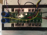
Indeed, I clearly heard the difference when I went from 1 pair of output devices to the 7 pairs. These 7 pairs where taken directly out of a tube (same batch). With the 7 pairs installed some detail was clearly gone, that's why I'm pulling my hair now if my matching afterwards was doen good enough. I'm assembling my second monoblock now, I only will add 1 pair of output devices in order to make a comparison between 1 pair and my 7 "matched" pairs of bjt's.
Hi Bensen,
I'll assume you added mosfets? You may rn into more of an issue with gate charge on the P channel devices causing distortion. Adding outputs will reduce the output impedance, but I think at 4 pairs you might be running into diminishing returns.
An easy test is to run them at idle once everything has warmed up and is stable. Do you get the same (or close) voltage drop across the source resistors? That will show you how good your matches are.
-Chris
Now Bensen, see if you can figure out what is going on based on these results:
Things to check:
- RE Resistor ratio
- VBE match
- Current ratio at quiescent
- Current ratio at 1A
Measure each VRE at quiescent and at 1A. I think with those measurements, we can figure it out.
Also, post a schematic.
Best, Sandro
Dear Sandro,
Here is what I'm able to measure:
1.Resistor ratio: Resitors are dale RS-2B 0R22 0,5% ==> Worst case:0R2198 -- 0R2211
2.VBE match @about 20°C : @100mA: 0,6396…..0,6406mV
3.Current ratio at quiecent:
@18°C: 105mA…112,3mA (based on voltages over emitter resistors)
@50°C: 105mA…113,2mA
4.Current ratio at 1A: Not able to measure this due to thermal problems
5.Hfe's @100mA: 99...108
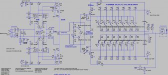
Below is the circuit as build.
Attachments
No. I'm on a motorbike. A car moves from A to B....Ever have a good front end alignment done in your car?
That was in a double-blind test?...I clearly heard the difference...
Indeed, I clearly heard the difference when I went from 1 pair of output devices to the 7 pairs. These 7 pairs where taken directly out of a tube (same batch). With the 7 pairs installed some detail was clearly gone, that's why I'm pulling my hair now if my matching afterwards was doen good enough. I'm assembling my second monoblock now, I only will add 1 pair of output devices in order to make a comparison between 1 pair and my 7 "matched" pairs of bjt's.
Hi Bensen, interesting that going from 1 pair to 7 pairs made things worse. Weird. But, it could be a bunch of things including:
- 7 pairs may loading the pre-driver output, the capacitance at that node went up 7X slowing the node down.
- A potential oscillation due to a decrease in stability of the amplifier - you increased the parasitic pole time constant quite a bit.
How did you decide 7 pairs was the right number?
Anyway, would be interesting to see what you find.
- Sandro
Last edited:
Dear Sandro,
Here is what I'm able to measure:
1.Resistor ratio: Resitors are dale RS-2B 0R22 0,5% ==> Worst case:0R2198 -- 0R2211
2.VBE match @about 20°C : @100mA: 0,6396…..0,6406mV
3.Current ratio at quiecent:
@18°C: 105mA…112,3mA (based on voltages over emitter resistors)
@50°C: 105mA…113,2mA
4.Current ratio at 1A: Not able to measure this due to thermal problems
5.Hfe's @100mA: 99...108
Below is the circuit as build.
1- Resistor match looks good. But, their effect on ratioing will be at 1 Amp, not iddle.
2. Delta is 1mV. BTW, you are running each pair 100mA? That is 700mA in just the output stage, that heatsink will be really hot.
So 1mV, is a ratio of exp(1m/26m)=1.0392x or 4%. This is quite good.
3. 113mA/105mA = ~1.06 or 6%. While not precisely what 2. predicts, but close enough within the margin of measurement error.
4. No worries, we know at 1A is about RE match which is already good.
5. Close enough.
Good to see that measurement matches theory within measurement error, but at this point, I don't think matching is your problem. I think you put way too many output devices. Given your supply voltage of 52V, this is a ~130W amplifier give or take into 8ohms, so 3 pairs is really all you need.
Last edited:
Dear Anatech and Sandro,
I will perform some 10kHz square wave tests in the next couple of days.
Indeed, I've not done this witu 7 pairs. With 4 pairs everything was rock stable.
7 pairs... let's see??
Why 7 pairs: I noted that in the Original thread of this amplifier. Please find here:
https://www.diyaudio.com/forums/sol...low-nfb-fet-front-bjt-ops-14.html#post6164872
I'll look at the thread. For reference, from Bob Cordell's book:
"A rule-of-thumb thus emerges: divide the rated power by 75 and round up to the next integer. This is the minimum number of output pairs recommended to satisfy this thermal criterion. A 400-W amplifier would thus require six pairs of output devices"
- Bob Cordell
For your amp, that works out to two pairs. I like being conservative too, so hence I recommended 3. You want to be even more conservative, then I would recommend 4.
Best, Sandro
Well Sandro, my calculation (link two posts back) are based on calculations with actual parameters used in the amp.
The output devices are temperature derated, page 2 in the spreadsheet. I have used the DC SOA lines from the datasheets, not the 10ms line!
On page 1 you have to input a worst case phase angle together with the impedance of the load. My input values are based on again actual speaker measurements from b&w and Sonus Faber speakers available on stereophile IIRC.
The rule of thump from Bob C. Is applicable for 8ohm loads probably.
Anyhow, I trust my calculations.
- Status
- This old topic is closed. If you want to reopen this topic, contact a moderator using the "Report Post" button.
- Home
- Amplifiers
- Solid State
- If you put new output transistors, class A/B, will tou match them?