The pole is not overbuilt. This design uses a four inch voice coil with an internal 4 inch diameter neo slug. The pole size is determined by the internal hole size of the neo, large enough to give adequate venting but not so large as to loose flux. You need a lot of neo to drive enough flux over a 35mm long gap!
Andrew
Andrew
Depth Charge posted:
With a smaller, lighter, thinner cone, though, you can see the impact of reflections. They will often show up as small bumps/peaks in the impedance trace.
In this case, neo magnets are a true blessing because you can make the motor so small. Our Extremis woofer for example has a motor that cannot be "seen" by the cone through the basket windows (which are quite open). The only reflections the cone can get are the basket arms and the bottom of the basket, both of which are as small as possible.
Henny posted:
AlNiCo is very available in the US as well... I think the first part of your statement - "cult following" says it all. There's also people who insist that you need to use 28 AWG single strand wire to run your speakers. And I will admit that AlNiCo (and the thin wires) can introduce some very euphonic effects! But they are usually considered a bad thing if looking for accurate reproduction.
I guess it comes down to what you want. If accuracy is a goal, then go with neo or ferrite. AlNiCo adds a nice warmth from the compression effects it offers, and if you desire that sound, then go with AlNiCo.
But just don't try to claim it's a superior magnet material to neo or ferrite, because except for its very high temperature handling, it's not.
Of course, the most common choke-point in flux flow is at the pole-backplate junction, and you can typically saturate the joint with either ferrite or neo.
Underhung really isn't that efficient of a design, in all reality. People talk about it like it's a great design, but in actuality it's pretty poor (typical underhung structures). Yes, the voice coil is covered with an equal flux field over its entire length; however, a LOT of the flux field is being unused!
Quick primer: efficiency is Mms and BL ONLY. Nothing else. Those two numbers dictate the efficiency of the motor. How well the motor couples to the air is a function of cone area, but for purposes of the motor it's just Mms and BL.
We'll assume in the following examples tha the Mms is the same (say you want to keep the Fs the same for a given driver design). We'll only look at how BL changes efficiency.
BL is a function of B (flux in the gap) and L (voice coil integrating that flux). You can maximize either or both. For the highest theoretical efficiency, you'd want to maximize both, meaning keep as much of the voice coil in the highest flux regions as possible.
For example, say you have a 5mm one way target for an Xmax. You have a 15mm tall top plate, and an 5mm long voice coil. That gives you 5mm either way before the voice coil leaves the gap. Great. Of course, that also means you're only using 1/3rd of the flux in the gap! Two-thirds of the flux in the motor is wasted ALL the time. You can't use it. But you do get to use all of the L! So underhungs are not good utilizers of B, but great utilizers of L. They don't integrate much of the flux, but use all the integration capacity of the voice coil.
Overhungs are actually a bit more efficient. same goal (5mm one way), reverse the numbers. A 5mm gap, 15mm long voice coil. The voice coil completely covers the entire gap, and integrates most of the fringe field as well. You'll typically find flux utilization rates in the 70-80% range for most overhungs. They are very good users of flux, but poor users of voice coil. They cover the gap and most (if not all) of the fringe field, but will "waste" some turns on the low strength limits of the fringe where they would be better used in the high intensity gap.
---SHAMELESS PLUG MODE---
Our XBL^2 motor is kind of unique. There are two (or more) high intensity gaps, and of course lower intensity fields outside each gap. In typical XBL^2 designs, you end up with ~60-70% of the total flux being used by the voice coil. We are an OK user of flux - you're always integrating one (or more) of the gaps, and a good chunk of the close-in flux (typically you use 70-80% of the flux in a motor). And you have a greater percentage of the windings in the highest flux field (the gap) and its immediate fringes. So you end up with efficiency in terms of BL close to or equal to an overhung.
The big advantage is that you can also use a voice coil nearly as short as that of an underhung, which means that you CAN - if desired - lower the Mms of the driver and raise efficiency even more.
---SHAMELESS PLUG MODE OFF---
Hennie,
I'm familiar with Tom Gallagher and CGN Audio Labs. The Beehive motor is similar to the Aura teardrop, in that it uses radial neo to create a gap. IMHO, it's interesting but I don't see any big advantages to that shape that you can't get with a standard buildup. It is, IMHO, more difficult to manufacture, and doesn't appreciably shrink the size of the cup. It also requires a much more costly manufacturing process in terms of forging and milling the steel (you can't stamp any parts of that motor). But it works very well as intended - high B field, long gap.
Bill,
That's the downside of neo type motors - thick poles are required to handle the flux, and even then you can saturate the **** out of the pole. Magnets outside the voice coil are a great way to go unless you simply need to have a physically small motor.
Dan Wiggins
Adire Audio
It can matter, in some cases. In general, the lighter/thinner the cone, and the wider the bandwidth the driver, the more problematic reflections become. For a big thick-walled heavy cone like on our Tumult subwoofer, reflections really aren't an issue. You can put the driver right up against a solid wall and barely see ANY blip in the impedance trace; the reflections from the motor are gone.If it's been disscussed tell me to shut up now. If not, how much of a factor do you folk think reflections from the cone, off of the magnet and then back out through the cone is an issue here. Obviously if it is a considerable issue then Neo has extra points here over standard ferrite magnets, no? Surely it is an issue with more and more driver manufacturers making more aerodynamic basket structures?
With a smaller, lighter, thinner cone, though, you can see the impact of reflections. They will often show up as small bumps/peaks in the impedance trace.
In this case, neo magnets are a true blessing because you can make the motor so small. Our Extremis woofer for example has a motor that cannot be "seen" by the cone through the basket windows (which are quite open). The only reflections the cone can get are the basket arms and the bottom of the basket, both of which are as small as possible.
Henny posted:
Alnico has a cult following in Japan. It is difficult to buy the 1500AL anywhere except in Japan. Also, the KS9800 is freely available in Japan, but not to the same extent elsewhere. Is it even marketed in the US? That might explain the material choice.
AlNiCo is very available in the US as well... I think the first part of your statement - "cult following" says it all. There's also people who insist that you need to use 28 AWG single strand wire to run your speakers. And I will admit that AlNiCo (and the thin wires) can introduce some very euphonic effects! But they are usually considered a bad thing if looking for accurate reproduction.
I guess it comes down to what you want. If accuracy is a goal, then go with neo or ferrite. AlNiCo adds a nice warmth from the compression effects it offers, and if you desire that sound, then go with AlNiCo.
But just don't try to claim it's a superior magnet material to neo or ferrite, because except for its very high temperature handling, it's not.
Neo can be used to make small, light motors. It doesn't really allow for MORE flux than ferrite, if you have free-reign in terms of weight/size. Neo is extremely strong, but will quickly saturate steel; that is one of the nice things about ferrite - it takes large cross-sections to get high flux levels in the gap, and that of course leads to large top plates. With neo, you can quickly saturate the steel, so you use less magnet and steel.Maybe Neodym can be used to make higher efficiency high XMAX drivers? Can underhung motors be a niche for Neodym, apart from the weight saving in prosound cabs? Dan's comment please...
Of course, the most common choke-point in flux flow is at the pole-backplate junction, and you can typically saturate the joint with either ferrite or neo.
Underhung really isn't that efficient of a design, in all reality. People talk about it like it's a great design, but in actuality it's pretty poor (typical underhung structures). Yes, the voice coil is covered with an equal flux field over its entire length; however, a LOT of the flux field is being unused!
Quick primer: efficiency is Mms and BL ONLY. Nothing else. Those two numbers dictate the efficiency of the motor. How well the motor couples to the air is a function of cone area, but for purposes of the motor it's just Mms and BL.
We'll assume in the following examples tha the Mms is the same (say you want to keep the Fs the same for a given driver design). We'll only look at how BL changes efficiency.
BL is a function of B (flux in the gap) and L (voice coil integrating that flux). You can maximize either or both. For the highest theoretical efficiency, you'd want to maximize both, meaning keep as much of the voice coil in the highest flux regions as possible.
For example, say you have a 5mm one way target for an Xmax. You have a 15mm tall top plate, and an 5mm long voice coil. That gives you 5mm either way before the voice coil leaves the gap. Great. Of course, that also means you're only using 1/3rd of the flux in the gap! Two-thirds of the flux in the motor is wasted ALL the time. You can't use it. But you do get to use all of the L! So underhungs are not good utilizers of B, but great utilizers of L. They don't integrate much of the flux, but use all the integration capacity of the voice coil.
Overhungs are actually a bit more efficient. same goal (5mm one way), reverse the numbers. A 5mm gap, 15mm long voice coil. The voice coil completely covers the entire gap, and integrates most of the fringe field as well. You'll typically find flux utilization rates in the 70-80% range for most overhungs. They are very good users of flux, but poor users of voice coil. They cover the gap and most (if not all) of the fringe field, but will "waste" some turns on the low strength limits of the fringe where they would be better used in the high intensity gap.
---SHAMELESS PLUG MODE---
Our XBL^2 motor is kind of unique. There are two (or more) high intensity gaps, and of course lower intensity fields outside each gap. In typical XBL^2 designs, you end up with ~60-70% of the total flux being used by the voice coil. We are an OK user of flux - you're always integrating one (or more) of the gaps, and a good chunk of the close-in flux (typically you use 70-80% of the flux in a motor). And you have a greater percentage of the windings in the highest flux field (the gap) and its immediate fringes. So you end up with efficiency in terms of BL close to or equal to an overhung.
The big advantage is that you can also use a voice coil nearly as short as that of an underhung, which means that you CAN - if desired - lower the Mms of the driver and raise efficiency even more.
---SHAMELESS PLUG MODE OFF---
Hennie,
I'm familiar with Tom Gallagher and CGN Audio Labs. The Beehive motor is similar to the Aura teardrop, in that it uses radial neo to create a gap. IMHO, it's interesting but I don't see any big advantages to that shape that you can't get with a standard buildup. It is, IMHO, more difficult to manufacture, and doesn't appreciably shrink the size of the cup. It also requires a much more costly manufacturing process in terms of forging and milling the steel (you can't stamp any parts of that motor). But it works very well as intended - high B field, long gap.
Bill,
That's the downside of neo type motors - thick poles are required to handle the flux, and even then you can saturate the **** out of the pole. Magnets outside the voice coil are a great way to go unless you simply need to have a physically small motor.
Dan Wiggins
Adire Audio
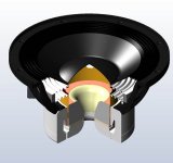
The pole is not overbuilt. This design uses a four inch voice coil with an internal 4 inch diameter neo slug. The pole size is determined by the internal hole size of the neo, large enough to give adequate venting but not so large as to loose flux. You need a lot of neo to drive enough flux over a 35mm long gap!
That's the downside of neo type motors - thick poles are required to handle the flux, and even then you can saturate the **** out of the pole. Magnets outside the voice coil are a great way to go unless you simply need to have a physically small motor.
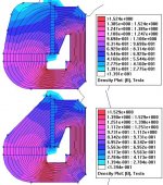
Sorry folks, I don't think I'm communicatin' here. I'm suggesting that, for magnetic purposes, the big shoulder at the top of the pole need not be there. If a picture's worth 1k words, a quick n' dirty FEA must be worth 1001, so here you go.
")
Top is the TAD motor (quite close, anyway). Bottom is same, only a couple lbs. lighter after a Dr. Bill diet. Density and distribution of B is identical.
The alteration of the pole vent profile would also serve to raise its resonance further out of the passband, I believe.
Bill
/likes nitpicking and worships efficient design
Attachments
Oh, I agree from a flux standpoint - they could definitely cut some out! And a lot out from other places, too! But it often comes down to a cost-benefit analysis. Sometimes it's lower cost to keep the steel there, and not machine it out (depending upon how the tooling for the forging is worked out). Live with a few extra pounds of steel to save $15 of machining work.
Also, sometimes you want a restriction in the pole to force some air back through the gap, to induce more cooling.
Definitely overbuilt from a flux standpoint, but there may have been other mitigating factors for the actual shape.
Dan Wiggins
Adire Audio
Also, sometimes you want a restriction in the pole to force some air back through the gap, to induce more cooling.
Definitely overbuilt from a flux standpoint, but there may have been other mitigating factors for the actual shape.
Dan Wiggins
Adire Audio
True, Dan. The devil is in the mitigating factors.
On another note:
Going slightly OT here, but your points above are why I personally like underhung for low-excursion apps, like mid/treble--full integration of the VC, so VC mass can be minimized. Where gaps are short, IMO you can often afford to trade flux utilization for minimum Mms.
For a high-excursion VC motor, however, I'd agree your XBL^2 brainchild is the benevolent king of topologies.
(Though I continue to be intrigued by the possibilities of the HyperDynamics topology, too...)
On another note:
So underhungs are not good utilizers of B, but great utilizers of L. They don't integrate much of the flux, but use all the integration capacity of the voice coil.
/snip
Our XBL^2 motor is kind of unique. There are two (or more) high intensity gaps, and of course lower intensity fields outside each gap. In typical XBL^2 designs, you end up with ~60-70% of the total flux being used by the voice coil. We are an OK user of flux - you're always integrating one (or more) of the gaps, and a good chunk of the close-in flux (typically you use 70-80% of the flux in a motor). And you have a greater percentage of the windings in the highest flux field (the gap) and its immediate fringes. So you end up with efficiency in terms of BL close to or equal to an overhung.
The big advantage is that you can also use a voice coil nearly as short as that of an underhung, which means that you CAN - if desired - lower the Mms of the driver and raise efficiency even more.
Going slightly OT here, but your points above are why I personally like underhung for low-excursion apps, like mid/treble--full integration of the VC, so VC mass can be minimized. Where gaps are short, IMO you can often afford to trade flux utilization for minimum Mms.
For a high-excursion VC motor, however, I'd agree your XBL^2 brainchild is the benevolent king of topologies.
(Though I continue to be intrigued by the possibilities of the HyperDynamics topology, too...)
I am sure i have seen the XBL design used in a few other woofers Rockford have a plate not a milion miles away from the ones on your models, a German company call ground zero have a baby version of your XBL plate, another called DD,,, you sure you got it protected Dan?
Whats the cost of the license anyway? what kind of royalties do you take?
Whats the cost of the license anyway? what kind of royalties do you take?
Bill,
One of the interesting "quirks" of XBL^2 is that it's nearly impossible to get a stroke LESS than 3mm... About the shortest Xmag I've been able to get is 2.8mm. Any less than that and the gap goes away - you end up with just a standard underhung. Kind of weird to have a motor topology with a MINIMUM excursion level!
And I've been talking with William of HyperDynamics - he's a very smart, interesting guy! There are some interesting things cooking up...
Paradise,
TTBOMK, neither Rockford nor GZ (or any of the other TC Sounds clients) use XBL^2. Lots of people use thick top plates, but that's not the technology. It's using multiple gaps within the motor that's the unique idea (gaps with flux in the same direction). I know it's unique because of some of the licensees we've signed up. Companies that have been around for decades, with 40+ year veterans really surprised by it.
Licensing - contact me off-line at dan (at) adireaudio (dot) com. There are a variety of licensing options...
Dan Wiggins
Adire Audio
There are some interesting things cooking up...
Cool.
I don't know if you're still aiming at the wacky-excursion market, but if whatever you're cooking up needs a nifty suspension concept with some pretty eye-popping characteristics, give me a jingle.
Bill, your FEA model is not a fully accurate representation of the magnet structure. It ignores the feature that redirects the flux path to give a more even distribution along the gap.
When this is included you get a slightly different result. A lot of FEA modelling was put into this design.
In addition all the pieces are turned, not forged. As Dan noted, it makes no sense to turn off more steel than one needs to. It just adds to manufacturing cost. Also, the magnet has to be fixed to the chassis. The area that is not machined away is the mounting surface to the chassis.
The shape of the vent hole was determined from airflow considerations. The smooth shape gives less "chuffing" at large excursions. The pole vent size in combination with the air volume under the dustcap forms a helmholtz resonator, like in a reflex cabinet, that does alter the response of the driver by potentially putting a dip in the response. A smaller diameter would actually move down the resonance, just as with a reflex vent and would result in more airflow noise. As this unit is intended as a woofer only, then air flow is more important than resonance frequency of any tuning effect. ( to move up the resonance, you would have to increase the pole hole diameter, taking away magnet area, or reduced the vent length, taking away excursion)
The tuning would be worse if the voice coil former was not vented. But by venting the coil you partially short circuit the pole vent resonance thus reducing it's severity. The coil venting is arranged so that it is not choked off at large inward excursions.
As you can see, there is a lot more to the design than just the flux path to consider!
Andrew
Hi Andrew,
Huh? The model was just eyeballed from the TAD pic, granted. But I looked reeeal close at that picture, and It looks very close to my sketch... Where is this 'feature that redirects the flux path?' I'll add it to my models and try again if you like...
Ok by me. TAD can use as much steel as they like. Better than using too little, I guess. Mitigating factors and all...
Hmm. Going solely from the picture again, I believe the basket is attached to the shoulder of the top plate, not the pole. The pole is all I suggested shaving... (If the chassis was mounted to the Pole, TAD would be getting an angry call from Volt's lawyer!)
Again, I can dig it. But just to be clear, I never suggested shrinking the vent diameter...
...Or flare a significant part of its length, as I pictured...
Amen!
Sorry if I offended anyone by calling this motor chubby. At the end of the day, it won't sound any worse for it. I guess I just bristle at the thought of good low-carbon steel going to waste.
Cheers,
Bill
/ore nugget hugger
your FEA model is not a fully accurate representation of the magnet structure. It ignores the feature that redirects the flux path to give a more even distribution along the gap.
Huh? The model was just eyeballed from the TAD pic, granted. But I looked reeeal close at that picture, and It looks very close to my sketch... Where is this 'feature that redirects the flux path?' I'll add it to my models and try again if you like...
As Dan noted, it makes no sense to turn off more steel than one needs to. It just adds to manufacturing cost.
Ok by me. TAD can use as much steel as they like. Better than using too little, I guess. Mitigating factors and all...
Also, the magnet has to be fixed to the chassis. The area that is not machined away is the mounting surface to the chassis.
Hmm. Going solely from the picture again, I believe the basket is attached to the shoulder of the top plate, not the pole. The pole is all I suggested shaving... (If the chassis was mounted to the Pole, TAD would be getting an angry call from Volt's lawyer!)
The shape of the vent hole was determined from airflow considerations. The smooth shape gives less "chuffing" at large excursions. The pole vent size in combination with the air volume under the dustcap forms a helmholtz resonator, like in a reflex cabinet, that does alter the response of the driver by potentially putting a dip in the response. A smaller diameter would actually move down the resonance, just as with a reflex vent and would result in more airflow noise.
Again, I can dig it. But just to be clear, I never suggested shrinking the vent diameter...
to move up the resonance, you would have to increase the pole hole diameter, taking away magnet area, or reduced the vent length, taking away excursion
...Or flare a significant part of its length, as I pictured...
As you can see, there is a lot more to the design than just the flux path to consider!
Amen!
Sorry if I offended anyone by calling this motor chubby. At the end of the day, it won't sound any worse for it. I guess I just bristle at the thought of good low-carbon steel going to waste.
Cheers,
Bill
/ore nugget hugger
DanWiggins said:
Most Ferrites are ground down to the 7-10 micron range prior to sintering, so that would be the size of the domain. But I think the whole "domain" concept is irrelevant! Why? Because the flux seen by the voice coil isn't directly from the magnet to the pole - it goes from the magnet to the top plate to the pole. The flux is channeled by the top plate.
This would be analogous to having a stream diverted to a channel via thousands of hoses. Yes, the flow is "quantized" by the hoses (flux quantized by domains). But you don't use the flux at that point - you use it at the end of the channel when it's "merged" again (at the gap).
I guess that, theoretically, this could be an issue for radially oriented magnets (where the magnets line the gaps). And IIRC both AlNiCo and Neo also have the 7-10 micron grain size. So a motor built with radial Neo would be the only one you could really say has discrete domains; any motor that uses steel to create the gap would not have this problem.
Hi Dan,
let me thank you for taking part in this discussion so intensively.
I agree that the Watkinson paper is mistaken on many points, and I have made my assessment in an older post that was linked to in this thread.
I am not sure, though, that your argument about the sintering grains holds.
From what I remember from my electrodynamics and thermodynamics classes (I'm a physicist), you get Barkhausen domains in any magnetizable material, be soft iron or any magnet material. It is a matter of self-organization. Think of any of these materials as being made out of miniscule individual permanent magnets. Let's call them elementary magnets.
Macroscopic view:
As long as the material in unmagnetized, the orientation of these is random, and the integrated field is zero. When you apply an external field, this field begins to align some of those elementary magnets, this reinforcing the external field. At some point, all magnets are aligned, and the material is in saturation.
Mircroscopic view:
This is where the thermodynamics come into play. If the elementary magnets were initially all randomly aligned, they would have a high energy and entropy, which is clearly not even a local mininum, i.e. not a stable condition. So they begin to form domains. In each domain, all elementary magnets are aligned, and in the unmagnetized state, the domains are randomly distributed and the macroscopic net field is zero.
As an external field is applied, some domains will grow at the expense of others. As self-organization and local energy minima are involved, the travelling of domain borders is not a continuous phenomenon, but takes place in the form of jumps which gives rise to the Barkhausen noise (the jumps are discrete, but not of equal size, hence the word quantized is unfortunate).
For the grains to hold up this process, there would have to be substantial voids between the grains or some modification on the surface of the grains that would keep the elementary magnets aligned in a particular orientation.
As I said, this effect will take place in any magnetic material, but the typical domain size and the amount of noise will depend on the material's properties.
There are only two cures for that: keep the AC field out of the iron and the magnet (copper ring) or keep the iron completely in saturation anywhere it sees the voice coil's field. This can be quite hard to achieve, most Nd motor designs I have looked at have most but not all of the pole piece saturated.
But I would not grow gray hair over Barkhausen noise, because noise is randomly distributed, and low level noise is probably the least offensive reproduction error. The nonlinearity of the hystersis curve of iron at the operating point is much more serious, because it gives rise to harmonic and intermodulation distortion. Fortunately, the cures are the same (shielding or saturation).
Greetings,
Eric
Bill,
brain freeze on my part about the fixing to the chassis. I was in a rush to go home!
As for the shape of the pole, I guess if you had the steel there to start with, why turn it all away if you don't have to. It takes more time to do this and time is money.
Keep up the critical analysis
Andrew
brain freeze on my part about the fixing to the chassis. I was in a rush to go home!
As for the shape of the pole, I guess if you had the steel there to start with, why turn it all away if you don't have to. It takes more time to do this and time is money.
Keep up the critical analysis
Andrew
Eric,
Good information, and it shows that the magnet material would be irrelevant; it's the steel - the part that makes the actual gap - that matters. If you have the same flux with the same grade steel, then the type of magnet will not matter in terms of Barkhausen. You don't cross the domains of the magnet, you cross the domains of the steel (unless you use a radial magnet structure).
Of course, the type of magnet, and it's coercive force will definitely affect how much flux modulation you get. That was my main point, especially with regards to AlNiCo.
Dan Wiggins
Adire Audio
Andrew: No worries--happens to me all the time, even when I'm not in a hurry. I'd like to write them off as senior moments, but I'm only 30...
Eric: Thanks indeed for your analysis of the root question of this thread. Good stuff.
Dan: Thanks for the backup of my first post about the importance of the gap. This opens a new can of worms--the question of steel's behavior in the dynamic conditions of a VC motor's magnetic gap.
I'll stir the pot with this excerpt from the SLMM whitepaper on ATC's website:
Of course, they advance SLMM as the answer, claiming a 10-15dB reduction in 3rd harmonic distortion through the midrange.
And one more thing:
So riddle me this: Does the HyperDynamics/DD topology in fact cause zero flux modulation through the magnetic circuit, regardless of magnet? Common sense tells me yes, but it seems too good to be true.
Eric: Thanks indeed for your analysis of the root question of this thread. Good stuff.
Dan: Thanks for the backup of my first post about the importance of the gap. This opens a new can of worms--the question of steel's behavior in the dynamic conditions of a VC motor's magnetic gap.
I'll stir the pot with this excerpt from the SLMM whitepaper on ATC's website:
The magnetic performance of steel is inherently non-linear. From work first published back in the ‘30s (mainly concerning transformers and rotating machines) hysteresis has been known to be at the root of the problem, with the induction of eddy currents a compounding factor.
Of course, they advance SLMM as the answer, claiming a 10-15dB reduction in 3rd harmonic distortion through the midrange.
And one more thing:
Of course, the type of magnet, and it's coercive force will definitely affect how much flux modulation you get. That was my main point, especially with regards to AlNiCo.
So riddle me this: Does the HyperDynamics/DD topology in fact cause zero flux modulation through the magnetic circuit, regardless of magnet? Common sense tells me yes, but it seems too good to be true.
Ok, Bill, caught me, I was sloppy. There is a third way to get rid of hysteresis, the ATC approach. It is to use a material anywhere where the AC field of the VC is significant that conducts magnetic flux but is not magnetizable. This is conceptually similar to keeping the iron in saturation, because saturated iron has a differentially non-magnetic, i.e. it will not change its magnetization if the AC field is smaller in amplitude than the amount by which the iron is driven into saturation by the DC field.
I am not sure what this material is and what its microscopic mechanism are, but as I said, Barkhausen noise is probably not the thing to worry about.
What is HyperDynamics/DD? Is this a fixed coil on the pole piece that is connected in series or parallel to the VC?
Greetings,
Eric
I am not sure what this material is and what its microscopic mechanism are, but as I said, Barkhausen noise is probably not the thing to worry about.
What is HyperDynamics/DD? Is this a fixed coil on the pole piece that is connected in series or parallel to the VC?
Greetings,
Eric
There is a third way to get rid of hysteresis, the ATC approach. It is to use a material anywhere where the AC field of the VC is significant that conducts magnetic flux but is not magnetizable. This is conceptually similar to keeping the iron in saturation, because saturated iron has a differentially non-magnetic, i.e. it will not change its magnetization if the AC field is smaller in amplitude than the amount by which the iron is driven into saturation by the DC field.
I hadn't thought of SLMM that way before, but I like your analogy--it's like having fully saturated gap faces at a very wide range of VC power levels. Beyond that, it also has the advantage of high electrical resistivity to discourage eddy currents.
I wonder what on earth it is... Some kind of powdered soft magnetic alloy in a ceramic matrix? A quick patent search didnt' help.
What is HyperDynamics/DD?
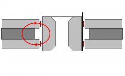
See this previous post for my quick n' dirty sketch. It's a dual-gap topology patented by HyperDynamics and licensed to Harmon. JBL calls it Differential Drive (DD). The flux flows into the pole across one gap and out across the other. The two VCs are on the same pole but they're counter-wound, effectively canceling their "pushes" against the B field, I believe.
Edit:
I attached a slightly less confusing version--stripped off the non-magnetic support structure to show the flux flow. Another nice thing about this topology is that any symmetrical flux gradients in the gaps that would otherwise yeild a tilted BL curve cancel in the integration of the two coils. Very slick.
Attachments
Yeah, there is widespread confusion about eddy currents, many people seem to think they are detrimental per se. It's a long time I looked at the ATC marketing mumbo, but I seem to remember they blew the same horn.
Eddy currents in any metallic material that is concentric to the voice coil are your friend, actually. The AC current in the VC induces a mirror current in the pole piece which acts to compensate and hence spatially confine the AC field.
The problem with mediocre electric conductors such as steel is actually only that the eddy currents are spread out over a larger volume. Copper has about 20x the conducitivty of typical steel. So 0.5 mm of copper will to the same shielding job as 10 mm of steel. With the copper, the whole pole piece is shielded. Without, a large percentage of the iron is unshielded or only partially shielded.
About DD:
When you take into account the nonlinear hysteresis curve of the iron, I think it will no longer work out perfectly, but it's too late now for me to think this through in any detail.
In the SLMM case, here's what the propaganda says:
Like you, I recognize the usefulness of Faraday rings in many motor designs, so by no means do I believe eddy currents are always your enemy.
I suppose the school of thought you choose to follow might be application dependant. In a woofer, might extensive Faraday treatment lower Qes too much for a desired bass response? (Hmm, I wonder if that's part of why JBL used alternating rings of steel and copper in the motor of the previously mentioned 1500AL--to encourage circumferential eddy currents but discourage motion-damping axial currents.)
Conversely, the ATC literature makes me wonder if the additional self-inductance they talk about might hamper treble response, if that's a design goal.
...secondly, the presence of the S.L.M.M. increases the self-inductance of the voice coil. When eddy currents are allowed to circulate in the system, they oppose the magnetic field producing them (i.e. that from the coil) and ‘cancel out’ much of the self-inductance. With the S.L.M.M. in place, eddy currents are suppressed and the self-inductance (i.e. the impedance) goes up.
thirdly, whilst the impedance, and therefore the fundamental voltage across a blocked coil goes up when the rings are fitted, the harmonic components, that are induced back into the voice coil, stay the same. This is because they are dependent only on magnetic field, which as we have seen, doesn’t change very much. The net effect is a rise in the signal/distortion ratio.
Like you, I recognize the usefulness of Faraday rings in many motor designs, so by no means do I believe eddy currents are always your enemy.
I suppose the school of thought you choose to follow might be application dependant. In a woofer, might extensive Faraday treatment lower Qes too much for a desired bass response? (Hmm, I wonder if that's part of why JBL used alternating rings of steel and copper in the motor of the previously mentioned 1500AL--to encourage circumferential eddy currents but discourage motion-damping axial currents.)
Conversely, the ATC literature makes me wonder if the additional self-inductance they talk about might hamper treble response, if that's a design goal.
- Status
- This old topic is closed. If you want to reopen this topic, contact a moderator using the "Report Post" button.
- Home
- Loudspeakers
- Multi-Way
- If neodymium is all that great . . .