Morgan L said:Yes, but maybe I was unclear. I meant tucking an LM317 between
cathode and ground of an ECL82 pentode section, to improve the
constancy of the current provided. There's only about 5-6V there,
so an IXYS wouldn't be happy, if I read the right data sheet in all
haste. It's a high-voltage part, and needs about 10V to regulate
properly.
(I bet it's much more expensive too, but that was not my point.)
Gotcha...
The ones i got were $1.40 USD...
dave
Thanks for all the great suggestions.
I am prity set on PRR's basic idea now.
If I used a LM317 in the tail would that be in place of the 170R cathode resistor or in addition. If in addition presumably it would involve referencing the grid to the top of the LM317 rather than the ground.
Shoog
I am prity set on PRR's basic idea now.
If I used a LM317 in the tail would that be in place of the 170R cathode resistor or in addition. If in addition presumably it would involve referencing the grid to the top of the LM317 rather than the ground.
Shoog
That would be instead of the resistor. The LM would have its
input connected to the tube cathode, adj. pin to ground, and
output via a current set resistor (ca 40 ohm) to ground (or
output when loading a common-cathode stage). The LM317
has a constant drop of 1.25V between its out and adj. pin,
so current is calculated as 1.25/R(current set).
The tube control grid goes to same point as LM adj. pin, pref.
through a 1k to prevent oscillation. (Tube grid could certainly
be biased positive to increase working voltage on LM, but I
don't see what good that would do - only a hotter chip...)
This page from TubeCAD shows the basic principle when used
as a cathode load CCS (can also be used as anode load, but
connection of the pentode screen may complicate things):
http://www.tubecad.com/february2000/page6.html
When used as a CCS, you don't want to use the cathode bypass
cap, since the point is that the high output impedance of the LM
will keep current constant and allow the tube g1 to move around
a bit as plate-cathode voltage varies. (Just a resistor won't do
as good a job in keeping it constant.)
I know there's more discussion and examples of this somewhere
else on TubeCAD, but I can't find it right now.
It would be far easier to hook up one of these IXYS thingies.
Only advantage of the chip/tube cascode is when heater comes
up, there is less of a transient on the output since the CCS won't
conduct until the other tube conducts. (There will still be some
wobble, though...)
Morgan
Just to clarify things (since I'm not quite sure anymore how you
wanted to possibly use an LM317)...
My rambling just above pertained to using the LM317 in con-
junction with an ECL82 pentode section, together working as
an efficient CCS, for the purpose of either loading the anode of a
common-cathode ECL82 pentode section, or for loading the
cathode of a cathode-follower connected ECL82 pentode section.
In both cases, the CCS pentode would be pentode-connected.
(And its current constancy would be improved. Enough to matter?
Who knows?)
The LM317 could also be used to set the bias of a common-
cathode, voltage/power amplifying stage, as in PRR's example
working into a 3k resistive or a 30mA/constant current load.
This is what the TubeCAD link illustrates.
The setup would be the same, except pentode cathode bypassed
for signal with a capacitor, and g1 driven, of course. Here, the
LM is only used to fix the idle current, and won't affect the anode
resistance, since the cathode is bypassed for AC.
Using an LM317 instead of a plain resistor in this latter case
seems of pretty limited use to me, to be honest...
Morgan
It was in using the LM317 in the cathode of a single pentode section of the ECL82, with the 3K anode load.
Heres another question, do you think that using a parafeed toroidal as per our discussion will produce a better result than the more conventional transformer loaded SE design ?
Shoog
Heres another question, do you think that using a parafeed toroidal as per our discussion will produce a better result than the more conventional transformer loaded SE design ?
Shoog
Shoog wrote:
"Heres another question, do you think that using a parafeed toroidal as
per our discussion will produce a better result than the more conventional
transformer loaded SE design ?"
That is a question I unfortunately cannot answer. I have never tried
a toroidal in parafeed. As I understand it, the toroidal must not be
too large, because a large one will not have enough primary induc-
tance, which will short low frequencies to ground and thus give weak
bass and earlier clipping.
If you can't get hold of those toroids any time soon - how about
looking for a pair of Hammond cheapos? Even 125Es will work if you
parafeed. And the 125(A-E)SEs will do both conventional and p-f,
so it's a pretty good investment, I think. (PCL82/partial FB/125BSE
in conventional SE is how I prefer to listen to HPs.)
Different PSU requirements? Yes, but it's easy to build a PSU that can
be modified to provide either B+ or 2 x B+. (How depends on trafo
config. - either stacking two secondaries or making a voltage
doubler if there's only one secondary.)
Also - not sure what would count as a better result. Measures
better? Or sounds better (to whom - a matter of taste, this)?
Resistive parafeed: more 2nd harm., warmer sound. And HP
listening can easily be too sterile, so this may be good. Also seem
to remember Steve Bench said something about experiencing a
certain magic in a resistive parafeed experiment he did...
http://members.aol.com/sbench/outstru.html
Oh, and some partial FB will remove some warmth if you get too
much...
Morgan
Hi Morgan,
It all been very informative and educational this.
Thinking about the LM317 as a CCS, I have a gut feeling that the benefit will be marginal and may even prove to be a negative. I once tried LEDS in the cathode of my ECC88 preamp and though initially impressed, found that with careful listening it was grainy so I went back to a resistor. You never know how these things are going to pan out, but if I read the TUBECAD article correctly, he came to the conclusion that on balance often the simplest implementation produced the most consistant and satisfactory result. Since the circuit is only called on to produce a modest output the problems of non constant current should be less than with a power amp (I hope).
In the matter of partial feedback - I hadnt really considered the need to up the current through the driver and so you point is well noted. Fortunately it shouldnt be to difficult to adjust the operating point if neccisary. I will start without. I intend not to bypass the cathode of the driver or the output tube so gain might start to become an issue if I reduce the anode load to any extent.
I remember the Steve Bench comment about the magic of resistive loading. The way I see it resistive loading can offer two advantages - at the cost of efficeincy, the resistive load will dominate the overall load on the Pentode/triode so allowing it to work more linearly. Of course this will tend to introduce more 2nd order harmonics. The other advantage is that it allows you to return the earth leg of the parafeed transformer to the top of the cathode resistor. This serves to introduce an element of feedback which will demonstrably stablize the overall output waveform.
My overall feeling is that an airgapped transformer is likely to introduce more distortion than a none airgapped transformer even with the additional distortion of the quality parafeed cap. Certainly if opting for one of the cheaper airgapped transformers their bandwidth is likely to be considerably poorer than a mains toroidal. The only really serious issue to consider with the toroidal is high frequency ringing, and so the need to for a scope to debug satisfactorily.
Of course this is the perenial argument between traditional SE advocates and the parafeed crowd, and there is no way that I am qualified to draw any useful conclusions. Still when efficiency is not a major consieration my overall feeling is to go for a simple restively loaded parafeed arrangement.
Still its incredible how many interacting options such a simple circuit presents.
Shoog
I think your reasoning makes sense and that you are moving in the
right direction, except one thing: not by-passing the output valve
cathode resistor. The resulting high anode resistance will give the
valve a hard time with low-freq. response. I think. Well, you'll see.
And partial feedback could somewhat cure this. A simple way to get
a negative voltage for the output grid, and thus avoid the problem
of cathode by-pass cap, is to put a resistor or a zener in the return
lead to the PSU, effectively creating a source of negative bias. The
last filter cap will have to go after this, from B+ directly to cathode.
I do this all the time, and it works fine for me.
I think you should draw something up now, post it for comments,
then go ahead and build. I don't think it's possible to predict any
further what topology you will like, so it's getting towards solder
sniffing time. Forget the LM317. And let the fun begin!
Morgan
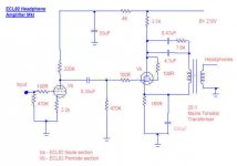
Looks workable to me. Pentode cathode resistor looks a bit small,
but I haven't analysed the loadline in detail. Might work.
I would at least halve the values of triode anode and cathode
resistors, but that's just me. Don't like starved operation.
The curious snubber across the parafeed cap - no, I won't ask,
just think the resistor value looks big...
"I decided not to try to include the partial feeback resistor. This is
because there is a sever mismatch between the two anode loads,
and I don't think partial feedback can be made to work in this
situation. "
The voltages on the respective anodes do not have to be the same
at all, just calculate current through resistor and add to/subtract
from the target value (of triode). But you may be right - with only
half B+ or so across the triode it won't be able to source/sink much
current, so you would have to use a big PF resistor, which may not
make much of a difference to performance.
Morgan
Hi Morgan,
The snubber is indeed a snubber. Works to kill the resonant frequency of the parafeed cap and transformer. With this in place I could probably lower the main parafeed cap to 1uf or even 0.47uf. This is standard practice over at the Bottlehead site.
Will build as is in the diagram, and can always mess with the bias point of the triode if necessary. This is the operating point shown on the datasheet.
The cathode resistor of the Pentode (in triode mode) is to give a grid bias of -5V at about 30mA so by my calculation it should be (5/0.030=166). Might need tweaking to get it just right.
Will keep you posted with progress, but it may be slow !!
Shoog
"The snubber is indeed a snubber. Works to kill the resonant
frequency of the parafeed cap and transformer. With this in place
I could probably lower the main parafeed cap to 1uf or even
0.47uf. This is standard practice over at the Bottlehead site."
Interesting! I guess it's been a while since I visited the Bottle-
head site...
I looked a bit closer at the load conditions, and - you're absolutely
correct, 166 ohms it is. Now my only worry is that you won't get
enough output with a 20:1 transformer. Might be enough for 32
ohm cans, but my beloved 300 ohm Sennheisers need about 5V
peak (OK, that's VERY loud...), so 5:1 would be better.
Of course, those 20:1 will at least tell you if the idea is worth
persuing. Hmmm, I wonder if those nice flat-pack, 4x12V 20VA
transformers on sale are useable for audio...
BTW, I get the 2nd harm. to 5.5 percent at max power - hope I
didn't get that wrong too. (CCS load would reduce that by 2/3,
it seems.)
Morgan
Hi Morgan,
I can re-adjust the transformers to make them 10:1 which should make them a bit more flexable. Unfortunately in that configeration the other 12V winding is left hanging which is bound to effect the output. Maybe a switching mechanism to switch the way the secondaries are wired up.
5.5% distortion is a bit brutal. Still I have set my heart against using another tube for a CCS. I was following the thread on Mosfet CCS which presents options. Don't know how easy it would be to sink a 100V over a Mosfet CCS. I suppose I can adjust the operating conditions on the Pentode to place 170V on the anode, and just sink 30V across the CCS. This would probably improve the distortion figures as well .
Shoog
5 % distortion sounds like a lot, but if it's mainly 2nd harmonic, and
only reaches this level on peaks and at extreme volumes... Your
ears will produce far more 2nd AND some 3rd! Just get the transformer
ratio right, and let's guess you typically "listen" to more like 0.5-1 %.
And 2nd H is pretty innocuous, as is well known.
I think it would be pretty easy to sink 100V/30mA across a CCS, with
a moderate-size heat sink on the power transistor or chip. There's the
IXYS part, otherwise Gary Pymm has suitable designs. Or one could
design one with e.g. a couple of DN2540 or similar depletion MOSFETs.
Come to think of it, I've done this, so I know it works. (150V/20mA plus
2 x 200V/10mA on the same sink - got pretty hot! For an OTL amp,
phase splitter/CF driver stages.)
About the output transformer - you should be able to connect the two
12V windings in parallel for 20:1 (12.8k:32 ohm) or in series for 10:1
(10k:100 ohm or 30k:300 ohm, etc.) in order to use all the copper. Just
get the polarity right... Experiment away!
Morgan
Hi there,
Got the mains transformers I am intending to use for output duty. Simple 12V mains toroidals. Modified the circuit it two respects. Left out the cathode bypass on the pentode, and also left out the lossy parafeed cap and resistor. Plugged the transformers in and fired up the amp for the first time. No smoke so I risked plugging in the headphones. Everything works first time. Nice clean sound even up to the top end. No obvious artifacts introduced from the output transformers. Everything sounds a little bass shy, but I think this is more down to the headphones (a pair of old sonys which I borrowed). Sensitivity is fine with a 20:1 ratio., half volume is fine for average listening levels.
The only real issue is that there is quite a nasty hum. I believe at least half of this is from the computers sound card, which I am using to drive them initially. The sound card puts out a bit of hum even with my main amp. However take out the source and at least half of the hum remains. Will need to poke around with the scope to track it down. Its not a soft 50Hz hum so its been generated somewhere within the circuit. When I move the circuitary away from the power supply it doesn’t change- so its not induced hum from the mains transformers (back to back 18V toroidals).
One observation I can make is that the headphones have a fuller sound than when i tried them through the headphone out on my friends solid state amp.
Shoog
A bit of poking aroundwith the probes has produced some interesting results.
The only really large hum in the circuit is to be found at the grid of the Pentode, which suggests that the triode is picking up a bit of hum from the input and amplifying it massively. The whole circuits earth is isolated from the mains and the case, so its not an obvious earth loop.
I'am thinking that the input impedance is maybe a little high at 220K, maybe if I reduce this it will reduce the hum, maybe not.
Shoog
Just a little more detail.
First I discovered I had wired the headphone socket incorrectly, so I sorted that out and things cleaned up a little. I also substituted 220K for the earth reference to the pentode grid whilst constructing. I have just replaced these with 560K resistors, again a little help.
The hum looks very dirty on the scope with plenty of high frequency crud and an overall 50hz characture..
It still seems as if the triode section is the main source of the hum. I have leads to the triodes anode from the main board. Maybe the anode is oscillating and picking up RF interference- should I include a small anode stopper? I only have 100R grid stoppers on the triode. I have seen 10K grid stoppers used on different ECL82 circuits - should I increase the grid stoppers?
Any help appreciated.
Shoog
Hi again,
I put anode stoppers on the triode sections - no significant difference.
I moved the amp to my main system to see how much of the hum was from my computer. The result was that the hum got worse. This leads me to suspect that its a simple ground loop problem (ha,ha,ha).
If I describe the grounding arrangement of my input phonos it might point up the problem. I have isolated input sockets from which I take a screened cable to the valve socket. On the phono socket both the signal core and the screen are connected. At the valve socket end again both the signal and the screen are connected. The signal comes in via a 100R grid stopper and at this point is referenced to the same earth as the screen via a 220K resistor.
So the isolated headphone amp star ground point is been contaminated by a connection to the outside world on the input phono socket, and hence back to the preamp.
The question is should I cut that connection at the valve socket, or the phono socket - or is there a better solution ??
Shoog
Shoog,
Hi again. Sorry, can't figure out what causes the hum or what you
mean about cutting ground connections (?). Any chance you could
make a drawing of your present circuit and post it?? It would be
so much easier to advise.
You must have a signal common point, so a solid ground connection
between signal source and HP amp is necessary. Seems OK so far.
Question is if you have some other ground connection between
said devices - such as a safety ground connecting the devices via
the mains socket... that could cause problems.
Grid stoppers are very close to grid pins, right? Signal-wise, AFTER
the 220k grid leaks? Anode stoppers won't do much good, and with
unbypassed cathode resistors, you effectively have cathode stoppers,
too, though this should be unnecessary with low-gm valves (might
help on a 6S45P, but ECL82 shouldn't need them!).
You say hum has mainly 50Hz character - not too "buzzy" sounding?
So could be heater? Are heater leads balanced with two 100 ohm
resistors? Raised above ground? Must at least be balanced to
make hum inaudible in headphones.
(BTW, seem to remember you mentioned somewhere, can't find it,
that you had a Lenco with broken arm bearings - might be able to
help you with new ones if that's still relevant!)
Morgan
Oh, forgot - bass shyness AND hum could possibly both be due to
not bypassing the pentode cathode. More heater leak voltage may
develop across the unbypassed cathode resistor; but more likely,
the anode load resistor will be small compared to the internal
resistance of the pentode's anode, so (almost) all B+ ripple will go
directly to the output.
And since the anode resistance (internal to the valve) will soar without
a bypass, it gets hard for the valve to develop voltage at low
frequencies, due to the finite inductance of the output transformers.
So, try temporarily a cap bypass to see if it helps! If you want to
avoid electrolytics, you could always try a series of diodes or LEDs
to bias up the pentode section. They won't increase the internal
anode resistance (significantly). (You could also experimant with
partial bypassing using a smaller cathode resistor in series with
LEDs or diodes. If there's still hum, it probably comes from the
input stage. A smaller HV cap directly from cathode to B+ will inject
antiphase hum Aikido-style - aka Ultrapath [?] - provided there is
at least some resistance between cathode and ground.)
G'night,
Morgan
- Status
- This old topic is closed. If you want to reopen this topic, contact a moderator using the "Report Post" button.
- Home
- Amplifiers
- Headphone Systems
- Ideas for using a pair of ECL82 in a headphone amp.