speedskater,
Along with following the national electrical code to the letter for your project I would install a totally separate, isolated earth ground. The standard NEC ground is a 10 foot long rod driven into the earth where all of the grounds eventually terminate.
For your audio room you can install a single separate ground going to a 10 foor copper rod driven into the earth as close to the audio room and as far away from the house panel.
I have this setup and I get zero transients from any electrical apparatus in my home. No hum, buzz, static just nothing on the ground side.
The power side is a lot more complicated. The isolation transformer is a good place to start. The hot side is much harder to completely isolate aside from using batteries.
Tad
So I took a quick look and see you are running a 200w amp and will possibly running a second. A dedicated circuit in your panel is not a bad idea. Everything else sounds like a waste of time and money.
The transformer, as was said before just a way of raising the supply impedance to your components. The direct connection to the utility system through your service panel will give you more instantaneous capacity. In an industrial setting you have to fuse for the interrupt capacity of the circuit, sticking a transformer (one to one transformer) between the bad boy outside reduces the size of the fault current. Other than making you feel you have something special you are worse off.
Running your power lines in a pipe, plastic, copper, steel, what is the point? Do you know why you are doing this? It will in no way add or subtract to the quality of the power you will have.
Plug all your components into one point to eliminate the problem of ground loops.
Solid core, stranded wire, it makes no difference. Use standard 12 gauge wire and be done with it. With the length of the run you have any more will not have an effect. Just more of a pain to hook up. Ohm's law is your friend.
You do not need anything special wire. Forget skin effect, capacitance, all the other reasons for different wires. You are transmitting 60Hz after all. The wavelength is so long you will not get any transmission line effect, any other exotic reasons you can think of.
Get a good surge arresters, if you want to spend some money get a whole house one and install it in your panel. Then put a secondary surge arrester at your components. This should kill any spikes that come down the line.
Not to be contrary but did you have problems with your stereo before that makes you want to take all these actions? Your home is not a harsh environment and what gets thrown to your components should be easily handled by them. Run cabling for sensors for hundreds of feet in industrial environments is a different story. Might be time for a little sanity check.
http://www.globalspec.com/FeaturedP.../SDSA_3650_Secondary_Surge_Arresters/109159/1
Hello, Tad.
I believe a single earth ground is all that is permitted for a single-service installation, and it has to be as close to the service entrance as possible.
I think someone mentioned earlier it plays havoc with GFI protected circuits when I mentioned the ground rod and they thought I was planning to do what you are suggesting (add a second ground rod).
However, I will mention that all our robot installations have an earth ground rod next to each robot, and we also have one on our grit blast cabinet to dissipate static charge. These were installed by the electrical contractors, so I guess there are cases where it is permitted... (but that is an industrial installation, not a home). Also the CNC machining centers have them as well I just remembered.
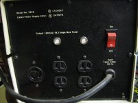
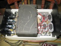
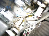
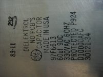
Attached are pics of the 'beast'. Seems to have a large transformer and 4 good sized caps... Star ground inside too! I'll gut the outlets out of it and probably just make a new end panel with two penetrations: in and out...
I believe a single earth ground is all that is permitted for a single-service installation, and it has to be as close to the service entrance as possible.
I think someone mentioned earlier it plays havoc with GFI protected circuits when I mentioned the ground rod and they thought I was planning to do what you are suggesting (add a second ground rod).
However, I will mention that all our robot installations have an earth ground rod next to each robot, and we also have one on our grit blast cabinet to dissipate static charge. These were installed by the electrical contractors, so I guess there are cases where it is permitted... (but that is an industrial installation, not a home). Also the CNC machining centers have them as well I just remembered.
Attached are pics of the 'beast'. Seems to have a large transformer and 4 good sized caps... Star ground inside too! I'll gut the outlets out of it and probably just make a new end panel with two penetrations: in and out...
Attachments
Not only is that against NEC / CEC rules, it's very dangerous!speedskater,
Along with following the national electrical code to the letter for your project I would install a totally separate, isolated earth ground. The standard NEC ground is a 10 foot long rod driven into the earth where all of the grounds eventually terminate.
For your audio room you can install a single separate ground going to a 10 foor copper rod driven into the earth as close to the audio room and as far away from the house panel.
I have this setup and I get zero transients from any electrical apparatus in my home. No hum, buzz, static just nothing on the ground side.
The power side is a lot more complicated. The isolation transformer is a good place to start. The hot side is much harder to completely isolate aside from using batteries.
Tad
Look through the papers that I posted links to at the start of this thread (post #2) and see if any of the paper recommend a separate ground rod.
It is amazing how many "know it all" are on this world - that give advises without bothering to read first a few links.
It is dangerous and banned by local and NEC codes to install a separate ground rod. Also it doesn't improve nothing in the audio power supply - the "pops" are coming from shared neutrals, undersized wiring, bad/old joints in the electrical path (like the in-out from the old receptacles).
Also suggesting USP systems for audio systems - that urban legend keeps popping everywhere on the net perpetuated by people that have no clue how an UPS is working and how "dirthy" is the output voltage.
What's next?
It might regulate the voltage, but if you read about how they are really working you will find out that are deforming the sin wave (therfore creating harmonics) and also there are terible slow to react to transient loads. Not what you want for an amplifier power supply.The presence of the big capacitors suggests that it is a ferroresonant transformer. It should work well for regulating voltage.
Last edited:
It is amazing how many "know it all" are on this world - that give advises without bothering to read first a few links.
It is dangerous and banned by local and NEC codes to install a separate ground rod. Also it doesn't improve nothing in the audio power supply - the "pops" are coming from shared neutrals, undersized wiring, bad/old joints in the electrical path (like the in-out from the old receptacles).
Also suggesting USP systems for audio systems - that urban legend keeps popping everywhere on the net perpetuated by people that have no clue how an UPS is working and how "dirthy" is the output voltage.
What's next?
It might regulate the voltage, but if you read about how they are really working you will find out that are deforming the sin wave (therfore creating harmonics) and also there are terible slow to react to transient loads. Not what you want for an amplifier power supply.
well mister know it all i have never seen" dirthy" voltage. but if it is good enough to run the worlds network every piece of medical equipment a hospital could have i don't know. how else are you going to have a supply void of noise, spikes and other transiants without a really good battery plant and inverter system. it's electricity inherently dirty and not pure. please correct me if i am wrong.
Hi Jim,
Just one comment. Well, maybe two.
Use only a single ground point for your electrical system. Aside from single grounds being code, multiple grounds (or "technical grounds") don't normally work well. What will help would be to confirm that the existing ground is a good one, and that the soil is always moist (I can't imagine why that's important! ). What you could do if needed would be to install a rod deeper into the ground. That's the solution for a ground spike not well installed.
Some recording studios I have done work in did try to use "technical grounds". They were a fad at one time, but they didn't work. The only sites still like this are the ones that Ontario Hydro doesn't know exist. As far as worrying about the conduit material, don't. Just go to code. Any situation a home will be in will not be helped by using a shielded (or magnetically shielded) conduit. Filters at your equipment end will be the proper way to deal with that. Note that you can also get entry filters intended to be installed right at the panel. They are ULC / UL / CSA approved devices. Same goes for surge protection devices.
If you know of a maintenance person for AM radio stations, talk to them. They have instruments designed to test the ground quality of grounding systems. In fact, they need to confirm large area grounds for the antenna systems.
The ferro-resonant transformer you have there does not output a sine wave. You probably want to rethink that idea. And yes, the power loss is significant as well as the fact that they can be extremely noisy in operation. These are used mainly to regulate the AC voltage, not to isolate noise.
A good isolation transformer built on an EI core that includes an electrostatic shield would be the device you are looking for to block noise on the line. Your amplifiers should probably go direct if they are high power, your signal equipment can go after the isolation transformer. I can see this working to attenuate the possible electrical noise you may have.
I moved into a new house about 10 years ago now. I was allowed to do extra wiring myself before the walls were closed up. All I did was run a heavier gauge wire to a dedicated outlet for my sound stuff. I used that for the amplifiers, and the normal power installation for my signal stuff. Yes, they are on the same phase. Really, that's all that was needed in my situation. No high power radio stations or heavy industry around here.
-Chris
Just one comment. Well, maybe two.
Use only a single ground point for your electrical system. Aside from single grounds being code, multiple grounds (or "technical grounds") don't normally work well. What will help would be to confirm that the existing ground is a good one, and that the soil is always moist (I can't imagine why that's important!
). What you could do if needed would be to install a rod deeper into the ground. That's the solution for a ground spike not well installed.Some recording studios I have done work in did try to use "technical grounds". They were a fad at one time, but they didn't work. The only sites still like this are the ones that Ontario Hydro doesn't know exist. As far as worrying about the conduit material, don't. Just go to code. Any situation a home will be in will not be helped by using a shielded (or magnetically shielded) conduit. Filters at your equipment end will be the proper way to deal with that. Note that you can also get entry filters intended to be installed right at the panel. They are ULC / UL / CSA approved devices. Same goes for surge protection devices.
If you know of a maintenance person for AM radio stations, talk to them. They have instruments designed to test the ground quality of grounding systems. In fact, they need to confirm large area grounds for the antenna systems.
The ferro-resonant transformer you have there does not output a sine wave. You probably want to rethink that idea. And yes, the power loss is significant as well as the fact that they can be extremely noisy in operation. These are used mainly to regulate the AC voltage, not to isolate noise.
A good isolation transformer built on an EI core that includes an electrostatic shield would be the device you are looking for to block noise on the line. Your amplifiers should probably go direct if they are high power, your signal equipment can go after the isolation transformer. I can see this working to attenuate the possible electrical noise you may have.
I moved into a new house about 10 years ago now. I was allowed to do extra wiring myself before the walls were closed up.
All I did was run a heavier gauge wire to a dedicated outlet for my sound stuff. I used that for the amplifiers, and the normal power installation for my signal stuff. Yes, they are on the same phase. Really, that's all that was needed in my situation. No high power radio stations or heavy industry around here.-Chris
Hi SoNic_real_one,
UPS systems come in many flavors. The main classifications are "on line" and off line", followed by sine wave (big, heavy and hot) and rectangular wave. What you would normally see are off line rectangular wave units intended for switching power supplies in computers. Trust me when I say that anything with a real transformer will probably draw huge current from these types of UPS devices (small wall warts seem to survive these). If you intend to power anything with a transformer, you need to use a sine wave type inverter. Newer approximations to a sine wave type UPS devices may or may not work that well. You can expect high harmonic content from these. At least they won't burn out a transformer though.
Hi scid714,
Medical equipment has input filters, electrostatic shields and lot's of HF filtering to begin with. Particular attention is paid to leakage currents though. The electrical service in a hospital intended to run medical equipment is normally filtered first, before distribution. Those are the orange colored outlets. The outlets you can plug your laptop into are normal power on a separate distribution.
"Dirty", or power that has a lot of noise riding on it, can be a real problem for test equipment. This is what medical equipment really is. Therefore a lot of effort is brought to bear on both sides of the plug to filter noise out. The filters inside equipment may also be their to keep internally generated noise out of other gear as well. Grounding on any test bench is critical, and normally engineered in some way. Even if the engineering was done for you in a power conditioner or distribution device / system.
-Chris
I know the difference between UPS systems and I know that even the "true sine" ones have a distortion level. The only "perfect" sine wave comes from a syncron generator.
That's why I am against using an UPS to feed a power amplifyer.
When I said "dirty" I was reffering to harmonics and HF noise.
As for other electrical issues discussed above - it "happens" to be that I am a licensed "master electrician" in VA. And working towards my EIT in electrical engineering...
That's why I am against using an UPS to feed a power amplifyer.
When I said "dirty" I was reffering to harmonics and HF noise.
As for other electrical issues discussed above - it "happens" to be that I am a licensed "master electrician" in VA
. And working towards my EIT in electrical engineering...OK. I guess the isolated ground and no transformer with #12 wire (maybe #10) is what the final solution is.
Anyone want a big heavy transformer?
The price of steel is going up. Could be worth a couple of bucks.
There are a lot of replies that jump back and forth between many aspects and I'm not sure what you've completely decided on, so I'm just going to throw my (licensed) 2 cents at what stuck out at me.
1/ Romex can not be ran within a conduit. The insulation is not rated for that use.
2/ Compression conduit fittings are unreliable for grounding purposes. In my neck of the woods it's required to run an additional ground wire when compression fittings are used rather than the screw type.
3/ Isolated ground recepticles are snake oil in residential applications. Everything must go back to the common service ground. Notice my use of "common".
4/ The only difference between solid and stranded wire for power distrubution is ease of handling.
5/ I have seen multiple ground rods in resi applications, but they were bonded together using appropriately gauged bare copper. That would obviously ruin what you're trying to accomplish.
I'm with ya Jarret!
If I run conduit, I will run stranded single wires in it, as one would expect. I will not pull romex through a pipe. I also want to twist the hot and neutral (and let the ground remasin straight) or litz braid the three together inside the pipe. Doing that might actually make it easier to pull...
If I use the compression fittings, I will jump across each pipe junction with a ground wire, or go with the set screw ones.
There will be only one ground for the entire structure (as required by code), and it is pounded into the ground outside the service entrance, where it should be. I will not add another ground rod.
Otherwise, I may just run romex across the house away from other wires, but otherwise 'open' across the floor joists for the first floor. It seems it won't be a problem at all this way. I hope we are collectively right, because I'd hate to have to pull it down and do it over!
Earlier tonight I moved my breakers down so this outlet will be fed from the top of the panel.
I won't do any further work on this for a couple weeks as I'm getting married Friday and then off to Spain for a week. Once the dust settles, I'll be back at it!
I also need to determine exactly where I want/need this outlet. The room is a bit oddly shaped, so placement of components is not intuative...
Hi SoNic_real_one,
The true sine wave UPS units have very low distortion that is comparable to what you would get from loading any service with a transformer - capacitor input filter type supply. If you look at the voltage waveform with an oscilloscope from an average residential service, you will normally see that the tops of the sine wave are flattened. The secondary of a transformer shows the same distortion.
The actual problem with the normal computer UPS is that the output is actually a positive square wave (or pulse really), followed by dead time and a negative going pulse of similar amplitude and duration, followed yet again by some more dead time. I have witnessed a small 3 KVA UPS with two additional battery packs destroy itself, and the (*expensive*) phone switch that used those ferro-resonant type power transformers (two of them in each tower). The switch in question was a double tower ITT 3100 system loaded up.
The death toll was:
The fact that I had advised strongly against this choice of UPS in favor of the sine wave type that should have been used didn't allow me to laugh. The dolt that installed this replacement backup power system was my supervisor. Ever try to obtain 4 replacement power supplies instantly, after hours? It was easy, he sent me to return to the warehouse and retrieve the power supplies and meet him back there. Needless to say, the UPS system, brand spanking new, was a total write-off. No, warranty didn't cover it. The batteries actually ruptured, all in a few furious moments of mutual destruction.
Okay, so the reason I posted what I did was that you wrote the following ...
Now, my comments were made knowing that other members will read this (and other information) and may possibly use it to make a decision. Also, I don't know what you know either. From your response, I had to assume you were not aware how many types of this equipment are actually available.
Gas generators are a poor power source for audio equipment, and especially Carver "magnetic field coil" type amplifiers. Similar results to the above story, but with a different cause. Carver "magnetic field coil" type equipment will run quite happily on a computer type UPS as long as you don't run it up. I'm sure there are other examples out there.
-Chris
Cool!I know the difference between UPS systems and I know that even the "true sine" ones have a distortion level.
The true sine wave UPS units have very low distortion that is comparable to what you would get from loading any service with a transformer - capacitor input filter type supply. If you look at the voltage waveform with an oscilloscope from an average residential service, you will normally see that the tops of the sine wave are flattened. The secondary of a transformer shows the same distortion.
The actual problem with the normal computer UPS is that the output is actually a positive square wave (or pulse really), followed by dead time and a negative going pulse of similar amplitude and duration, followed yet again by some more dead time. I have witnessed a small 3 KVA UPS with two additional battery packs destroy itself, and the (*expensive*) phone switch that used those ferro-resonant type power transformers (two of them in each tower). The switch in question was a double tower ITT 3100 system loaded up.
The death toll was:
- 4 - Ferro-resonant power supplies.
- 2 - battery packs full of brand new gel-cells
- 1 - battery set in the main inverter (gel cells again)
- 1 - Brand new 3 KVA APC online UPS
- 1 - Customer confidence
The fact that I had advised strongly against this choice of UPS in favor of the sine wave type that should have been used didn't allow me to laugh. The dolt that installed this replacement backup power system was my supervisor. Ever try to obtain 4 replacement power supplies instantly, after hours? It was easy, he sent me to return to the warehouse and retrieve the power supplies and meet him back there. Needless to say, the UPS system, brand spanking new, was a total write-off. No, warranty didn't cover it. The batteries actually ruptured, all in a few furious moments of mutual destruction.
Okay, so the reason I posted what I did was that you wrote the following ...
Your comments did not include the possible use of the sine wave type of UPS that would work quite well for power backup for almost any type of equipment. So by not responding in a complete manner to a reasonable question, you were actually wrong in your response. Remember that many people do not have the knowledge you have, so any statements you make in response to a question should be complete, or limited in scope with the limits made clear.Also suggesting USP systems for audio systems - that urban legend keeps popping everywhere on the net perpetuated by people that have no clue how an UPS is working and how "dirthy" is the output voltage.
What's next?
Now, my comments were made knowing that other members will read this (and other information) and may possibly use it to make a decision. Also, I don't know what you know either. From your response, I had to assume you were not aware how many types of this equipment are actually available.
Gas generators are a poor power source for audio equipment, and especially Carver "magnetic field coil" type amplifiers. Similar results to the above story, but with a different cause. Carver "magnetic field coil" type equipment will run quite happily on a computer type UPS as long as you don't run it up. I'm sure there are other examples out there.
-Chris
Ground fault interrupters (GFI's) do not monitor ground currents and could care less where your grounds are. They look at differential hot-neutral current, assuming any difference is due to a ground fault. Think about getting a jolt while mowing your lawn- the ground fault occurs on your front lawn, far away from your service ground. GFI circuitry has no connection to ground at all:
LM1851 - Ground Fault Interrupter
LM1851 - Ground Fault Interrupter
Ground fault interrupters (GFI's) do not monitor ground currents and could care less where your grounds are.
I understand that, but the building code requires/allows only one ground point, and it is supposed to be as close to the service entrance as possible to abate a lightning strike on the pole from frying your house as it seeks a good ground through the structure (and usually ignites it in the process). So, if your 'new' ground point happened to have a more favorable path to ground than the required one at the service entrance, the strike would come through the house and find that better ground. I see both sides, and I have decided to stick with one ground.
There are certain circumstances where more are allowed.
That's EXACT the problem. World is full of "know it all" people that give advises in matters they should't. If you cannot imagine the bad situation, doesn't mean that is not existing. Just go with what the electrical codes and licensed electricians tell you.Ground fault interrupters (GFI's) do not monitor ground currents and could care less where your grounds are. They look at differential hot-neutral current, assuming any difference is due to a ground fault.
See below.
I know. But none of them is made to follow a fast-variable load libe the audio amplifyer, they are build for quasy-constant loads. And when they follow the variable load, the distortion level is way higher than the advertised one.Hi SoNic_real_one,
UPS systems come in many flavors. The main classifications are "on line" and off line", followed by sine wave (big, heavy and hot) and rectangular wave.
And to make matters worse - yes, the transformer might have let-trough a second harmonic, but that's easy to filter, while the switching noise in the "true-sine" output is in the kHz range and it is not easily filtered by power supply stages of audio equipment.
All in all, even a "true sine UPS" it will sound bad.
Attachments
Last edited:
-use a separate 10 ga. solid core, 20A ckt for power amp.
you need high peak currents, not voltage regulation.
-remember 20A outlets
-skip UPS or xformer here
-use a separate 12 ga. solid core, 15A ckt for everything else.
-modify inside audio gear as needed to filter power.
btw, what is your transformer k-factor rating?
you need high peak currents, not voltage regulation.
-remember 20A outlets
-skip UPS or xformer here
-use a separate 12 ga. solid core, 15A ckt for everything else.
-modify inside audio gear as needed to filter power.
btw, what is your transformer k-factor rating?
- Status
- This old topic is closed. If you want to reopen this topic, contact a moderator using the "Report Post" button.
- Home
- Design & Build
- Construction Tips
- "Ideal" power line from Service Panel