Seems to be issue with using LT1016
Seems to be issue with using LT1016, lot of ringing at the edges, May be too fast for this application. 10ns !, need to look at comparators that are around 40 - 80 ns. Do any one faced this issue ?.
Planning to replace it with LM360 or LM319 + Transistors.
Seems to be issue with using LT1016, lot of ringing at the edges, May be too fast for this application. 10ns !, need to look at comparators that are around 40 - 80 ns. Do any one faced this issue ?.
Planning to replace it with LM360 or LM319 + Transistors.
Hi-Res Schematic and enhancement
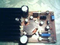
I am working on modifying the out put stage to deliver 250W RMS, i can even expand it further to about 500W, but i don't have a suitable load to test, and use the woofers neighbours will be at my door")
I will soon post the hi resolution schematics and the PCB layout for this amplifier
I am working on modifying the out put stage to deliver 250W RMS, i can even expand it further to about 500W, but i don't have a suitable load to test, and use the woofers neighbours will be at my door
I will soon post the hi resolution schematics and the PCB layout for this amplifier
Congratulation
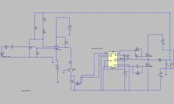
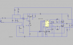
The comperator A1 in your schematic, is that the LM319 you are talking about a few posts back? How is it configured?
Guess the schematic is not entirely as build.
What output mos are you using ... can't read it of your schematic picture.
What modifications are you planning, for raising the output capability to 250-500 W?
Have you done any measurements on the amp (distortion etc.)?
looks really promising
Looking forward to hearing about your further research/trails
Thumbs up
Schematics and components
Yes, the schematic is not matching completely with the built unit as in the photo because i drew the schematic using LTSpice where there is no model for LM319N( LT / Philips) and IRF540Z( Not IRF540N ). LM319N should be used in place of the op amp shown. The inverter should be replaced by HCT4069 or HCF4070/HCF4030.2200uf capacitors should be added close to the mosfet leads that is not shown in the schematic. I didn't get MURS120 so i used BYV27-200. The transistors in the level shifters are BC547 and BC556.The regulator transistor is MJE13007.
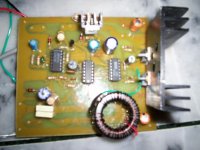
Yes, the schematic is not matching completely with the built unit as in the photo
because i drew the schematic using LTSpice where there is no model for LM319N( LT / Philips) and IRF540Z( Not IRF540N ). LM319N should be used in place of the op amp shown. The inverter should be replaced by HCT4069 or HCF4070/HCF4030.2200uf capacitors should be added close to the mosfet leads that is not shown in the schematic. I didn't get MURS120 so i used BYV27-200. The transistors in the level shifters are BC547 and BC556.The regulator transistor is MJE13007.- Status
- This old topic is closed. If you want to reopen this topic, contact a moderator using the "Report Post" button.
- Home
- Amplifiers
- Class D
- IC version of UCD