Hi! fi have a problem with my MX50 x2. i buy this tansformer 300W 220V Toroid Transformer for Amp 28V 0 28V 12V 2 6V | eBay then i buy this power supply board Assembled Nover Rectifier Power Supply Speaker Protection Integrated Board SN | eBay and i buy 2 mx50x2. I gathered mx50, connected to the power supply board and transformer. And one of the boards mx50 burned. In what may be the reason? where to look? or advise another set of amplifier
Hi! fi have a problem with my MX50 x2. i buy this tansformer 300W 220V Toroid Transformer for Amp 28V 0 28V 12V 2 6V | eBay then i buy this power supply board Assembled Nover Rectifier Power Supply Speaker Protection Integrated Board SN | eBay and i buy 2 mx50x2. I gathered mx50, connected to the power supply board and transformer. And one of the boards mx50 burned. In what may be the reason? where to look? or advise another set of amplifier
All it would take is the bias pot adjusted to the wrong end of its travel on 1st power up.
I'm sorry, but I do not quite understand you (I do not know much English). Do you mean that I need Bias pot? i have it. P7 Mini Preamplifier Board Top Pre Amp Headphone DIY Kit for MX50 L20 L6 NE5532 | eBay
Youtube is an excellent resource for learning about how circuits work.
"Bias" has to do with current being drawn through the circuit with load, but no source. It has to do with the amplifier's functional circuit.
If your board "burned" it is probably not useable. Sorry.
I can't say know much about MX50 boards, but hope this points you in the right direction.
I highly recommend you stick with it - learn as much as you can on your new hobby. Good luck!
I have four 2sa1941 and four complementar 2sc5198
Can I use this output transistor with the mx50x2 modifying the layout?
If it's not possible can you explain me the rails caps mods? The caps is connected from v+ to? From v- to?
And what is the problem with the trim of the bias?
I had to modify the circuit like post 17?
can I use the standard mx50 board with two sanken 2sa1693 and complementar 2sc4466?
Thanks")
Can I use this output transistor with the mx50x2 modifying the layout?
If it's not possible can you explain me the rails caps mods? The caps is connected from v+ to? From v- to?
And what is the problem with the trim of the bias?
I had to modify the circuit like post 17?
can I use the standard mx50 board with two sanken 2sa1693 and complementar 2sc4466?
Thanks
Last edited:
One certainly does need local decoupling at a distance of an inch or so.
That inch or so implies a minimum flow and return circuit length of >50.8mm
That is enormous.
Yes. And we don't know the exact ESR and inductance of reservoir capacitors (which are in the audio path...) Thus, I always put 1 uF film capacitors directly soldered on the PCB with short leads from rails to the output gnd (same as the Zobel Network). Correct wiring is mandatory, with 1.5 mm² (min) wire (+ - and gnd)
Another questionnable matter is the lack of small resistors (~47 ohms) in the emitters of input transistors ; very helpful in order to improve stability. And in the emitters of current mirror also.
Paulcar
I finally got around to building the MX50.2. I managed to lose one of the C1815 transistors and I was looking for a replacement. I found the online C1815 datasheets all indicated ECB as the connections but this did not correspond to the board which requires an EBC transistor!
One of the boards have the C1815 as supplied installed but I am reluctant to take out one of these and test it to confirm the connections are EBC. I even tried the datasheet for the 2SC1815 but that also shows ECB... any ideas?
Original Japanese TO92 transistors such as 2SC1815 are universally ECB components. They are long obsolete, so what is now sold is most likely an unbranded substitute, marked like the original but with goodness knows what specification or pinout. If you don't test what you have though, you will never know.
There are several other existing threads for this amplifier kit, discussing problems with copies of LJM's design kit. Some appear to use his PCBs too, adding confusing version numbers of their own. Like most Ebay kits, there are many pirate variations of the original with substitute parts that don't simply drop in so advice here may not be relevant to your kit. Have you checked that the PCB tracks have not been altered to suit the ECB pinout?
Here in post #4 is an early schematic where no 2SC1815 are used, just another pair of BC546 which are EBC, of course: http://www.diyaudio.com/forums/solid-state/216609-ljm-mx50-kit-amp.html
MX50/2
Noted. I have not been able to dertermine the quiescent current setting.
I have read the entire thread and altho there have been enquiries, I dont see
any answers. I would expect a current of between 100ma and 200ma for
class AB operation. Any info? I have not an analyzer and this is required
to set the current for lowest distortion.
MX50.2
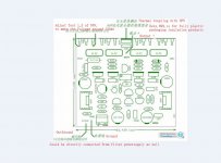
I would put a meter in series with the +50v supply and adjust the bias for the recommended level of quiescent current but I cannot find any recommendation from the designer of the kit. I can get at the emitters of the output transistors
which are connected to 0R15 resistors (supplied instead of 0R22 as stated on the board)., but it would be easier to measure the total current Perhaps someone has information on the level used by Musical Fidelity in their XA50?
- Home
- Amplifiers
- Solid State
- I tried the eBay MX50 DIY Kit, Class AB 100W+100W; Worked but problem