isn't it easier to use an integrator(with extra input opamp.) in front of the Tripath amps. so you could easily undo the offset while maintaining 0V offset at the output and have dc coupled inputs. Pity you have to use the integrated input opamp in the Tripath amp. At least the input caps. are biased.
Another thing to try really
Another thing to try really
Is it possible to not use the integrated opamp in the amp1B model? I don't think so.panomaniac said:Ummm.... Not really sure what you mean there.
But you can go in past the onboard opamps. Just have to be carefull with grounds, DC offstes and such.
To use an integrator opamp. to get rid of offset is often used in poweramps to arrange dc coupling and have no cap. to ground in the FB loop.
I'm either VERY brave or a complete idiot, but I just DC coupled my AMP3 to my Entech DAC and didn't use a single external component.
I know I just mentiond I ordered some zeners to test this setup out, but I'm a bit impatient.
Here's what I did.....
I disconnected the signal ground from the board and attached it to the biascap side of C26.
Thats it!!!!!
I didn't use a zener, 22uf cap, or ferrite beads and there is NO extra noise on the output. The best thing is that the DC offset on both channels didn't change at all. It's still the same 60mv and 71mv it was before.
Unless someone can give a reason to add any of the parts I didn't add; I'm just going to leave them out.
This was easy for me because my power supplies ground is already isolated and the whole setup was sitting on my desk waiting to be tested.
This is great, no more "is this cap good enough?" doubts running through my head anymore.
Here is a pic of the DC coupling from the OPA2134PA in the Entech DAC straight to the AMP3. You can see the signal ground attached to C26.
An externally hosted image should be here but it was not working when we last tested it.

theAnonymous1 said:Dare I say; "uncolored".
Now I'm going to go find the info on nulling the output offset. Then I'll have a "T-Amp" thats DC coupled and offset free.
Sweet! nice job
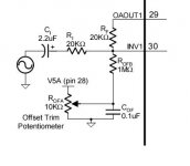
Well done. Look in the schematic for nulling the output through the LF411N integrator:theAnonymous1 said:This is great, no more "is this cap good enough?" doubts running through my head anymore.
http://www.grotel.nl/photo/wiringschemecrescendo2.jpg
Sorry Bgt, I'm a noob and can't make heads or tails of that sch.
I've been looking at the DC trim circuit for the TA2024C but I'm a bit confused and I think it's Tripaths fault. It says to connect one end of the trim pot to "V5A(pin 28)", but V5A on the chip is pin 9 not 28.
The circuit also needs a ground point but I'm not sure if that point would be power ground or my new input ground point at the biascap.
Man it s*cks being noob.
Attachments
Very cool!
But..... How do you control the volume? With the DAC?
Looks like you caught a big mistake on the Tripath sheet. Yes, it should be pin 9 NOT pin 28. 28 is a a speaker output! They must have pulled that note of a sheet for another chip and forgot to change the numbers.
I've used this offset null circuit many times, it works great. The Trends TA-10 has it too, minus a few bits.
Bgt said:Is it possible to not use the integrated opamp in the amp1B model? I don't think so.
Why not? Just go in via pins 22 & 25. You'll have to deal with the 2.5V bias and be sure the opamps on the chip are not making noise, but it should be possible.
The onboard opamps are just there as an input buffer. Plus the DC bias thing.
panomaniac said:Very cool!
But..... How do you control the volume? With the DAC?
Looks like you caught a big mistake on the Tripath sheet. Yes, it should be pin 9 NOT pin 28. 28 is a a speaker output! They must have pulled that note of a sheet for another chip and forgot to change the numbers.
I've used this offset null circuit many times, it works great. The Trends TA-10 has it too, minus a few bits.
For right now I'm just using the digital volume control from the PC its connected to. There will be a pot in there once the amp is cased up.
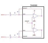
It seems Tripath needs to proof their files a little better. They made another mistake in the datasheets that show how to bridge their amps. You can see in the attached pic that RI goes into the OAOUT2 side of RF when its supposed to go to the INV2 side; just like it does on INPUT1. This caused me a bit of a headache when I was trying to bridge an AMP1-B.
So whats your guess as to where I should ground the DC trim circuit now; power ground or signal ground? Also, I only have 50k trim pots, no 10k. Will it still work?
Attachments
this schematic is a way to try to nul the offset. Don't know if the amps. inverts or not. Otherwise you have to put the integrator on the - of the OPA. Did not try this myself on the AMP1B. So values can be wrong because offset at the OPA output should be nearly 2.5V. Just a guess.
http://www.grotel.nl/photo/integratoramp.jpg
http://www.grotel.nl/photo/integratoramp.jpg
theAnonymous1 said:There will be a pot in there once the amp is cased up.
I'm pretty sure you're going to get massive DC offset once you put a pot in there. Any DC path to ground will cause DC offset, even 1M. I know, I've done it.
But you aren't connected to the normal analog ground now, so who knows? Try a high value resistor, like 500K between input + and your new ground point to see what happens. Don't connect your speakers!
I think the null offset circuit is going to be connected to analog ground, as it would be normally. Just gotta try it and see.
I'm pretty sure you're going to get massive DC offset once you put a pot in there. Any DC path to ground will cause DC offset, even 1M. I know, I've done it.
A pot should be OK. I checked for voltage between the input and new ground and there isn't any. I even completely shorted the inputs to the biascap pin and it was fine.
I guess I'll flip a coin on which ground to connect the DC trim and hope luck is still on my side.
BTW, I've been listening to the amp for 4 or 5 hours now and I have to say.... WOW. I recall reading somewhere around here recently about some holy grail $300 teflon caps. I thinks it should be more like a $300 teflon band-aid. Caps Shmaps!!!!! Use a peice of wire.
theAnonymous1 said:
It seems Tripath needs to proof their files a little better. They made another mistake in the datasheets that show how to bridge their amps. You can see in the attached pic that RI goes into the OAOUT2 side of RF when its supposed to go to the INV2 side; just like it does on INPUT1.
Hi,
the figure you showed is the normal TA2022 input stage. That attached is the bridged configuration in TA2022 datasheet.
Congratulations for your experiment. Any hope to have a schematic for a TA2022 without input caps?
Attachments
the figure you showed is the normal TA2022 input stage
You're correct it is the normal input not bridged that I posted, but the drawing is still wrong as I explained(?).
I'm not very good at drawing up schematics, but you really don't need one it's so simple.
Basically just wire the inputs without any caps, but instead of connecting the input ground to analog ground; connect it to the biascap pin. Then you just need to make sure the analog ground and your source ground are isolated and that the source has no DC.
I'll probably do this to my AMP1-B tomorrow if I have time.
Its so simple I'm surprised it's taken untill now for someone on this forum to try it out. Maybe I was more willing than others to destroy an amp.
theAnonymous1 said:I checked for voltage between the input and new ground and there isn't any. I even completely shorted the inputs to the biascap pin and it was fine.
Oh, duh!
Of course! Your new ground point is at 2.5V already. Should have seen that before.You're a brave man. It's a cool idea, but you need to be extra careful about what's upstream of the amp. What happens if the ground is no longer floating? Maybe nothing. Your DAC may already be grounded via the computer.
No hum? Sometimes I find the amps need to be grounded to kill hum, but that's usually before I put the lid on. Hmmm.....
- Status
- This old topic is closed. If you want to reopen this topic, contact a moderator using the "Report Post" button.
- Home
- Amplifiers
- Class D
- I hope nobody takes this the wrong way...