Here is one that managed to give me the slip!
# 5: Hypex documents mention 'earthing/grounding' the modules via metal stand-offs to the system chassis. This is a good practice to keep EMI at bay. But please be aware this has no other role. Hypex modules do not rely on this 'earthing/grounding' for their proper functionality, either with regard to audio signals or digital control signals. All control signals are referred to the SMPS ground. Also, the balanced audio lines, by design, are ground agnostic--the shields over the signal cable lines only serving to provide EMI shielding.
It has been reported in my circle that a particular sequence of these 'earth/ground' connections will eliminate 'ground loops' and insure proper functionality of the modules. This is likely to be so, AFAIK, for those who subscribe to the view that your hair should be parted exactly in the middle while listening to stereo signals in order to maintain proper balance! (So sad the baldies like me get dumped!)
Audio, after all, is a highly subjective domain!!
--UKP
DLCP
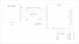
As outlined earlier, the DLCP is the system controller, and in order to take advantage of its features like stand-by, triggered fom the remote control, the DLCP should remain powered by a Standby power source. For reference, the DLCP-SMPS recommended by Hypex and its connection with the DLCP are given in the block diagram.
When the main power switch is thrown on, in the default condition, both the V+/- supplies and the standby rail (+8V) are on. For initiating the standby mode, the microcontroller issues a shutdown command for the main V+/- rails. Hypex documentation is not very clear about certain aspects, but it is obvious that the micro-controller and its allied digital circuitry remain powered by the always-on Standby rail, while the signal processing circuitry are powered by the V+/- rails. Upon receiving a wake-up command from the remote, the controller pulls the power control line to (LO), switching on the main power rails.
Kindly also note that the DLCP provides separate SMPS-ON and AMP-ON control signals. In various scenarios, a mix of these control signals could be used in a complex system. The individual DLCP outputs J10 to J15 are particularly convenient for system builders, each connector offers two lines carrying the balanced audio +/- signals, the third happens to be the shield/ground and the fourth wire carries the Amp-on, active low control signal--this could trigger on either an SMPS (with its feed to the amp module via the Auto amp-on line), or an amp module when fed to the Amp-on pin directly.
Hypex approves of the DLCP module being operated from the auxiliary V+/- rails of the standard SMPS (like the 400A) that power the amp modules. However, kindly note that Standby mode can be entered only when an external standby voltage is fed into J17 (+8V, with the 0V rail going to Ground).
Many builders make use of small, cheap switching supplies here as they believe it is not critical, as it only powers the digital circuitry.
However, more than once it has been reported that the use of a "cheap and cheerful" PSU here 'somehow' affected the sound quality of the DLCP outputs. Builders have, to my knowledge, experimented with DIY regulated power supplies built to high specs, which have 'restored' the audio quality. This is getting a mention here as it will be foolish to brush under the carpet such claims without ample experimental evidence, which surely is within the capabilities of the average experimenter. One particular builder has gone to the extent of claiming 'fabulous' improvement when he employed twin transformers and regulators, one set for the V+/- rails and the second exclusively for the Standby rail powering the micrco-controller and the associated digital circuitry.
Objective auditions are called for here before favouring one or the other approach.
--UKP
Attachments
SYSTEM OPTION-1
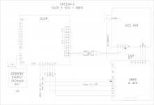
Let us take a look at the 'standard' option of an all-Hypex system.
The system has the DLCP and its recommended SMPS, amp modules like the UcD 400 or 180, and their associated SMPSs.
The hookup is pretty straightforward. As recommended earlier, the Auto amp-on feature is used, the relevant SMPS in its turn getting triggered by control signals from the DLCP.
Other options will be examined in future posts.
--UKP
Attachments
SYSTEM OPTION-2
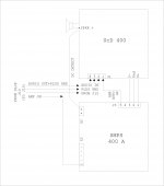
The second option available to the builder is to run the DLCP from the SMPS powering the amp module.
SMPSs like the A400 provide a couple of auxiliary V+/- rails (about 20V) which will handily power the DLCP. But the caveat is that in order to be able to use the remote-triggered Standby mode, you need to plug in an external supply of +8V/1.5 A, which remains 'live' while the main SMPS/s go to sleep in Standby mode. Do make sure that the 0V line (Ground) has continuity with the SMPS ground. (DLCP J17 pin#2 is Gnd.)
The wiring up is straightforward, with the DLCP triggering the SMPS off and on, the amp modules getting turned on by the relevant Auto amp on signal.
Attachments
SYSTEM OPTION-3
System Option # 3 (that many "traditional" builders might prefer for reasons of their own) chooses to replace the DLCP SMPS with a transformer powered linear PSU. This option is likely to generate a fair amount of opinion and findings, pro and con.
In this connection I think it is only fair on my part to remind ourselves that it has not been long since many subscribed to the view that "digital was digital", and a digital signal was identical to its copies, and that there was no room for any thought about noise etc in that domanin. I might be oversimplifying things a bit here, but the truth is that subsequent research and careful subjective auditions have banished such thoughts. Today the fine distinctions in audibility of signals output by USB ports, optical connectors etc, the audibility of jitter in many situations etc are receiving unbiased and unopinionated attention. It is in this backdrop I am proposing that the findings of a few DIYers about the positive audible improvements brought on by a linear PSU to the outputs of the DLCP should be investigated further. Hence the proposal for replacing the Hypex DLCP SMPS with a traditional linear PSU.
Looking at the system hookup, it is no different from System Option-1, with just the DLCP-SMPS getting substituted by the linear power supply. A single transformer with multiple windings, or two separate transformers might be used, with +/- 18 V @ 500 mA, low-ripple/noise regulated outputs for the DLCP main supplies, and a +8V @ 1.5 A, preferably regulated, supply to feed the standby pins of the DLCP. The idle power consumption of the linear supply while in the standby mode could be ignored. The amp modules and their associated SMPSs could be fed audio and control signals by the DLCP J10 to J15 connectors. As mentioned previously, the Pin#4 control lead could be cut to provide the trigger for the SMPS via J5#1, while SMPS J3#5 Auto amp on could be spliced onto the cut half feeding J1#1 of the amp. This ought to ensure a smooth and artifact-free turn-on of the SMPSs and the amp modules.
Please be careful about grounding. The Hypex modules do not make use of the chassis ground, except for EMI elimination. So one many confine the chassis ground to interconnecting the mains earth and the EMI-earthing metal standoffs of the modules, as also the heatsinks. As for the linear supply, DO NOT connect the 0-Volt common line/s to chassis ground. Just connect the main V+/- and the Standby supply 0V lines together, and wire it up to the DLCP GND pin. That should take care of the proper functioning of all the modules.
As an aside, the above should be the approach with speaker lines too. (Loudspeakers are inherently differential devices and they are ground agnostic in their functionality.) Yesterday I came across some SNAFUs created apparently by our general practice of employing the "star earth" concept while wiring up high current output stages and loudspeaker connections. Here we can safely ignore all such ideas and wire up the loudspeaker lines (both + and -) fully floating, connected directly to their terminals on the amp modules, and to nowhere else. Unnecessary and arbitrary "earthing" to chassis ground can create more problems than solve any in the case of the Hypex modules, AFAIK.)
Show me the audibly significant measured differences between the mains freq PSU and SMPS at the output of the amplifier module.It is in this backdrop I am proposing that the findings of a few DIYers about the positive audible improvements brought on by a linear PSU
It is in this backdrop I am proposing that the findings of a few DIYers about the positive audible improvements brought on by a linear PSU to the outputs of the DLCP should be investigated further.
Indeed. I am sure those DIYers know something that Hypex doesn't.
")
Looking forward to the results of the investigations, especially the measurements and double blind listening test results.
Yes, indeed, auditioning would seem to be a sensible approach!!......
Many builders make use of small, cheap switching supplies here as they believe it is not critical, as it only powers the digital circuitry.
However, more than once it has been reported that the use of a "cheap and cheerful" PSU here 'somehow' affected the sound quality of the DLCP outputs. Builders have, to my knowledge, experimented with DIY regulated power supplies built to high specs, which have 'restored' the audio quality. This is getting a mention here as it will be foolish to brush under the carpet such claims without ample experimental evidence, which surely is within the capabilities of the average experimenter. One particular builder has gone to the extent of claiming 'fabulous' improvement when he employed twin transformers and regulators, one set for the V+/- rails and the second exclusively for the Standby rail powering the micrco-controller and the associated digital circuitry.
Objective auditions are called for here before favouring one or the other approach.
--UKP
Show me the audibly significant measured differences between the mains freq PSU and SMPS at the output of the amplifier module.
Yes, that is an impediment to understanding a lot of what is perceived in their auditioning.
Yes, that is an impediment to understanding a lot of what is perceived in their auditioning.
The lack of objective data?
I would express it as the lack of data that correlates to how audio devices sound but not willing to get into the usual silo warfare on thisThe lack of objective data?
I would express it as the lack of data that correlates to how audio devices sound but not willing to get into the usual silo warfare on this
At least we agree on the lack of data.
Yes, when standing by.
The rail current should rise in normal working mode.
I took the value of maximum rail current from the Hypex recommendation, which pegs it at 1.5 A max. Please see the Hypex specs.
Please have look at de DLCP datasheet, not the smps ( not correct!).
THE OBJECTIVITY/SUBJECTIVITY CUSP
I stand corrected about a slip that I made.
"...Objective measurements and careful auditions are called for here before favouring one or the other approach..."
My feeling is that though one might look at the specs and measurements very critically, what gives one real satisfaction in the end is when the equipment proves to sound good to your ears. I do not wish to say that hearing is everything, but at the same time I have no hesitation to say that I will not retain something that sounded awful after a long enough period of listening, in spite of its first-rate and certified measurements.
My intention in sharing my take on system building was intended to help at least those DIYers who faced problems. I myself had found the lack of hand-holding guidance from Hypex (they do reply to your emails, and are helpful, but a set of typical system configurations and some do's and don'ts would have taken care of the needs of those who are not inclined to study all the technical manuals as if they had to take an examination.) vexing indeed. Also, certain simple faux pas (like the unnecessary grounding etc) would often create problems. I couldn't understand why many builders, who were quite knowledgeable about amp building, had run into troubling SNAFUs-- more than some others who were good at "join the dots" sort of system building.
The inexplicable behaviour of the DLCP in many scenarios unfortunately was on account of lack of ground continuity and also due to the lack of the standby rail, which drove the DLCP into an indeterminate mode. There are quite a few such things that had come to my note over the past year or so. Hence my step-by-step approach to system building, which, if it proves to be a reliable summing-up and a broad road-map for the average builder,would be more than ample reward for me for sticking my neck out in a forum.
Who haven't been part of the endless objective/subjective debate, at least as an interested bystander/lurker??
Many of us are in the hobby because we feel we could glean better value for money, and satisfaction. The forums also have the advantage of hosting many knowledgeable designers and builders for whom making money from their designs is not the be all and end all. The spirit of healthy debate and co-operation has more often led to most satisfactory results all around. Quite a few among us, though competent in construction, may not be at home when it comes to refining a design or employing advanced measurement techniques to prove a point. Naturally, these aspects are taken up by those who have proven competence in such areas. What happens is that these collective discussions and debates serve as guidance to a larger body of enthusiasts who filter these many inputs to come to their own conclusions and realizations of projects.
I am sorry, but I am not here to open again such debates, which I leave to specialists. I did NOT say that I OBSERVED improvements with a PSU substitution. I brought such a claim --not an isolated claim-- advanced by more than one builder, and after careful and critical listening tests by a group (please! dont bring up again all those points of double-blind testing etc) of DIYers, that such an improvement was audible, which they could not explain in any way, with the thought that this would attract an expert look into the claim.
For somebody with a working system, and who is equipped to undertake objective and scientifically valid measurements, it would be next to nothing to plug in a substitute power supply, do a set of measurements and auditions, and publish the results. Simple!
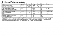
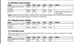
Here I am also attaching the specs of the Hypex DLCP. Kindly note the Standby rail voltage and current. The 30 mA is while the DLCP in Standby mode.
Kindly note a correction also.
The DLCP main power supply rails are +/- 16 V typical and NOT +/- 18 V as I had posted earlier. My apologies.
--UKP
I stand corrected about a slip that I made.
"...Objective measurements and careful auditions are called for here before favouring one or the other approach..."
My feeling is that though one might look at the specs and measurements very critically, what gives one real satisfaction in the end is when the equipment proves to sound good to your ears. I do not wish to say that hearing is everything, but at the same time I have no hesitation to say that I will not retain something that sounded awful after a long enough period of listening, in spite of its first-rate and certified measurements.
My intention in sharing my take on system building was intended to help at least those DIYers who faced problems. I myself had found the lack of hand-holding guidance from Hypex (they do reply to your emails, and are helpful, but a set of typical system configurations and some do's and don'ts would have taken care of the needs of those who are not inclined to study all the technical manuals as if they had to take an examination.) vexing indeed. Also, certain simple faux pas (like the unnecessary grounding etc) would often create problems. I couldn't understand why many builders, who were quite knowledgeable about amp building, had run into troubling SNAFUs-- more than some others who were good at "join the dots" sort of system building.
The inexplicable behaviour of the DLCP in many scenarios unfortunately was on account of lack of ground continuity and also due to the lack of the standby rail, which drove the DLCP into an indeterminate mode. There are quite a few such things that had come to my note over the past year or so. Hence my step-by-step approach to system building, which, if it proves to be a reliable summing-up and a broad road-map for the average builder,would be more than ample reward for me for sticking my neck out in a forum.
Who haven't been part of the endless objective/subjective debate, at least as an interested bystander/lurker??
Many of us are in the hobby because we feel we could glean better value for money, and satisfaction. The forums also have the advantage of hosting many knowledgeable designers and builders for whom making money from their designs is not the be all and end all. The spirit of healthy debate and co-operation has more often led to most satisfactory results all around. Quite a few among us, though competent in construction, may not be at home when it comes to refining a design or employing advanced measurement techniques to prove a point. Naturally, these aspects are taken up by those who have proven competence in such areas. What happens is that these collective discussions and debates serve as guidance to a larger body of enthusiasts who filter these many inputs to come to their own conclusions and realizations of projects.
I am sorry, but I am not here to open again such debates, which I leave to specialists. I did NOT say that I OBSERVED improvements with a PSU substitution. I brought such a claim --not an isolated claim-- advanced by more than one builder, and after careful and critical listening tests by a group (please! dont bring up again all those points of double-blind testing etc) of DIYers, that such an improvement was audible, which they could not explain in any way, with the thought that this would attract an expert look into the claim.
For somebody with a working system, and who is equipped to undertake objective and scientifically valid measurements, it would be next to nothing to plug in a substitute power supply, do a set of measurements and auditions, and publish the results. Simple!
Here I am also attaching the specs of the Hypex DLCP. Kindly note the Standby rail voltage and current. The 30 mA is while the DLCP in Standby mode.
Kindly note a correction also.
The DLCP main power supply rails are +/- 16 V typical and NOT +/- 18 V as I had posted earlier. My apologies.
--UKP
Attachments
@ ds23man
Thank you for that warning shout!
That woke me up, and I did take a good look at the DLCP spec sheet.
You are right!
Hypex say the DLCP V+/- typically is 18 V @ 500 mA, while the standby voltage is 8 V @ 40 mA max.
I had thought that when you chose to substitute one piece of equipment with another, you followed the specs of that one. How foolish of me!
When it comes to the petite DLCP SMPS, Hypex say the typical V+/- voltages are only 16 V @ 500 mA and the standby rail is 8 V @ 1,500 mA. Ah, maybe Hypex thought that hobbyists have ample ESP to figure out all these mysteries. So much for their data sheets... And thank you ds23man for your eagle eyes.
However, I feel that feeding a connection that needs 40 mA with 1,460 mA more is not going to bring the skies down. Had I sleepily typed 18 V instead of 8 V, this ought to have merited a loud vocalization, no doubt. Perhaps ds23man, living so close to Hypex, could kindly choose to wake up Hypex, and correct THEIR document.
REVISED RECOMMENDATIONS
In the light of the above discoveries, my double apologies to anybody who follows these Hypex system configuration guidelines.
The linear power supply that would replace the DLCP-SMPS is going to be a simple affair. Use a 750 mA or 1 A transformer and wire in two standard 1A regulators that would give you +/- 18 V. For the Standby supply, solder in a 9 V mini-reg, and you are done!
Now forget all about currents, and boldly go where no man has gone before and occupy that comfortable "hot seat" and begin the critical audition. Measure, if you know how to, to your heart's content. And always wear a safety helmet while posting!
Warm regards to all!
--UKP
Attachments
- Home
- Source & Line
- Digital Line Level
- Hypex DSP module(s)