So other than GND and NC, that leaves:
J1.4: Current Limiting Monitoring (Output)
J1.5: Amplifier Ready (Output)
J1.9: Clipping Detection (Output)
Am I right that these last three don't have a simple connection anywhere on the DLCP or SMPS? What is their purpose? Are they just there to drive LEDs for instance, to give a visual warning of these conditions? Or could they be used to control the SMPS or DLCP somehow?
If my assumptions so far are correct, and these pins are only for displaying various conditions in the amplifier, then I may attempt to hook them up to LEDs on my front panel. So I'm after some electronics advice.
J1.4 is the 'Current limiting' output. It goes low when the amplifier is limiting, so I want an LED that lights when this pin goes low.
J1.9 is the 'clipping detection' output. It goes low when the amplifier is clipping, so again I want an LED that lights when this pin goes low. Pull-up resistor needed according to the spec sheet.
J1.5 is the 'Amplifier ready' output. It goes high when the amplifier shuts down due to an error. So I think I want an LED that lights all the time (showing that the amplifier is ready), but which goes out when the pin goes high.
So I think all of these LEDs require the same sort of circuit - one which puts the corresponding pin output onto the cathode, so that the anode and the cathode are at the same voltage unless the pin goes low, at which point the LED lights. Am I on the right lines? I don't know the first thing about such a circuit (yet), so I'm looking for advice on sourcing LEDs suitable for the voltages and currents that the UcD400OEM needs/provides, as well as what resistors to use, and how to approach the pull-up resistor that the 'clipping' pin needs (the 'limiting' pin is apparently 'internally pulled up').
I'm also thinking I don't want a whole bank of these LEDS on my front panel - one for each condition should suffice - but I want the clipping and current limiting LEDs to light whenever *any* of the amplifiers is in that state, and I want the 'ready' signal to go out whenever *any* of the amplifiers shuts down. I think that means I can tie all the 'clipping' and 'limiting' pins together, but some other type of logic is required for the 'ready' signals.
I'm envisaging a separate PCB to drive these LEDs using the outputs from the amplifiers. Any advice (and circuit diagrams!) would be most welcome.
The 20 A current will of course only be for very short peaks, average current will be much lower.
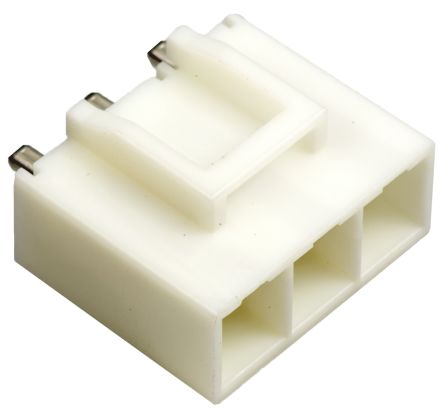
I just noticed this description of the 36-way header J1 on the UcD400OEM: "...one standard 2.54mm pitch dual row 36 pin header, current rating 3A minimum". So that's 3A per pin.
The power supply rails use 4 pins each, which means Hypex expect them to carry 12A, and the speaker positive and negative use 5 pins each, so 15A.
...I may change my board layout (again) to replace the 10-pin header with a 5-pin header to carry these three pins (in case I need them in future) plus the DC-Error output and the SMPS ON/OFF output, and add a jumper to select which ON/OFF signal to obey.
I've deleted the 10-way header, and replaced it with a 5-pin header with just the pins that I think I need.
An externally hosted image should be here but it was not working when we last tested it.
So the amp enable pin (EN) can either take a direct connection from the SMPS, or can be jumpered to EN_J2 to use the amp enable signal on the J2 Molex plug (which will come from the DLCP in my case).
The DC_Error signal (DC) is next to the EN pin, so that a two-pin plug can connect back to the SMPS.
Clipping detection (CLIP), current limiting (SCL) and Amp ready (SDA) are all available on adjacent pins so that I can run them to a PCB (yet to be designed) to control some front panel LEDs.
I don't think I need a GND pin, because the UcD modules get their GND from the SMPS, so the 'amp enable' and 'DC Error' pins will be referenced to the same ground as the SMPS ground. But I think I might need a GND pin as a reference for the 'clipping', 'current limiting' and 'amp ready' signals, depending on where the PCB for those LEDs gets its power from.
Well I think I figured out how to make use of the 'clipping', 'current limiting' and 'amplifier ready' pins. I think these schematics show what needs to be done to make them light up some LEDs, so I'm thinking I might put the corresponding LEDs on my adapter board. Ultimately I think I'd like to have one LED for each condition on the amplifier faceplate, but the schematic for that can be a job for another day.
I also added an option to use a pre-installed pull-up resistor for the 'DC Error' pin, as instructed in the UcD400OEM documentation. I'm not sure if I can tie all 6 DC Error pins together *after* they are individually pulled up, so while I figure that out I've added an option to disconnect the pull-up resistor by removing a jumper.
Here are my schematics - resistor values still to be calculated depending on the LEDs I choose.
Feel free to point out the obvious blunders!
And here's my current draft of the PCB.
* Dimensions adjusted to suit the UcD180 and the UcD400,
* LEDs along one edge,
* jumpers added to disconnect the 'DC Error' pull-up resistor and to select which 'Amp On' signal to use (SMPS or DLCP),
* and ground planes on both sides to make sure the LS- and GND terminals aren't restricted.
Work in Progress:
I also added an option to use a pre-installed pull-up resistor for the 'DC Error' pin, as instructed in the UcD400OEM documentation. I'm not sure if I can tie all 6 DC Error pins together *after* they are individually pulled up, so while I figure that out I've added an option to disconnect the pull-up resistor by removing a jumper.
Here are my schematics - resistor values still to be calculated depending on the LEDs I choose.
Feel free to point out the obvious blunders!
An externally hosted image should be here but it was not working when we last tested it.
And here's my current draft of the PCB.
* Dimensions adjusted to suit the UcD180 and the UcD400,
* LEDs along one edge,
* jumpers added to disconnect the 'DC Error' pull-up resistor and to select which 'Amp On' signal to use (SMPS or DLCP),
* and ground planes on both sides to make sure the LS- and GND terminals aren't restricted.
Work in Progress:
An externally hosted image should be here but it was not working when we last tested it.
An externally hosted image should be here but it was not working when we last tested it.
My sums for for those resistors. It would be good if someone was able to check my interpretation of the way these pins operate, and also my calculations.
Clipping Detection:
An open collector, that gets pulled low when there's clipping. I have to pull it to a positive voltage, max 65V, with a pull-up resistor, keeping the current below 100mA. That maximum of 65V suggests it may have been designed to be pulled up to the voltage of the SMPSXXXA400, i.e. 63V. So if I make R2 a 100K pull-up resistor, the current will be only 0.6mA, and the resistor has to cope with 40mW. Easy.
If I want to drive an LED from this pin, then that 63V supply needs care. A typical LED will drop 2-3V, so R1 has to drop around 60V, and unless I choose a low current LED then the power requirement for R1 will be quite high. So I could use a 2V, 10mA LED, which means I need R1 to be (63-2)/0.01 = 6k1. So if I use a 6K2 resistor, the power requirement is 61^2/6200 = around 0.6W. So a 1W, 6k2 resistor seems ok.
Current limiting:
This one is different. It's internally pulled-up, and goes low in the event of an error. If I'm reading the provided circuit diagram correctly, then it's limited to 5.6V under normal conditions, but drops to -VB (-63V) when there's an error. So R3 needs to do the same job as R1 if I want to light an LED when this pin goes low. So with another 2V, 10mA LED I need the same 1W, 6k2 resistor here.
Amp Ready:
This is different again. It's internally pulled up when there's an error. I think the diode in the circuit diagram limits the high voltage to 5.6V. Since it's named 'Amplifier Ready', rather than 'Amplifier Error', I think the idea is that it could drive an LED when everything is OK, but turn it off when there's an error. So in that respect it's a similar circuit to 'current limiting' above. I need the LED to be on when the pin is at -VB (-63), but off when the pin goes high to 5.6V. So in fact it's the same circuit as the current limiting circuit, meaning R4 is the same 1W, 6k2, and the LED is also 2V, 10mA.
DC Error:
There's no point in having an LED here since the point of this pin is to turn off the power supply ASAP, which means there'd be nothing to drive an LED. It's an open collector which goes low when there's an error, so all I need to do is pull it high so that the power supply doesn't randomly switch off due to a floating voltage which might be interpreted as 'low'. I'd like to provide a suitable pull-up resistor on my adapter board, but I also want the possibility to tie together all these pins from multiple amplifier channels, since there's only one 'DC Error' input to the SMPS. If I didn't have an on-board pull-up resistor I think I could tie them all together and pull them all up with a single resistor. So I *think* my on-board pull-up resistor needs to have a high value so that one channel going low pulls all the tied pins low and triggers the SMPS to shut down. In other words, the combined resistance of, say, 6 of these on-board pull-up resistors in parallel needs to be no less than what a suitable value would be for a single channel. I've read that 10k-20k would be ok if there was only one channel, so I *think* that means 100k on each board would sum up to be less than 10k even with 10 channels, so the tied together outputs would still go low if only one of the amplifier channels experienced a DC fault. I'm a bit unsure about this point (hence the jumper on my PCB), so would appreciate some expert advice.
In fact, I'm quite unsure about all of this, so once again, please feel free to point out any blunders!
An externally hosted image should be here but it was not working when we last tested it.
Clipping Detection:
An open collector, that gets pulled low when there's clipping. I have to pull it to a positive voltage, max 65V, with a pull-up resistor, keeping the current below 100mA. That maximum of 65V suggests it may have been designed to be pulled up to the voltage of the SMPSXXXA400, i.e. 63V. So if I make R2 a 100K pull-up resistor, the current will be only 0.6mA, and the resistor has to cope with 40mW. Easy.
If I want to drive an LED from this pin, then that 63V supply needs care. A typical LED will drop 2-3V, so R1 has to drop around 60V, and unless I choose a low current LED then the power requirement for R1 will be quite high. So I could use a 2V, 10mA LED, which means I need R1 to be (63-2)/0.01 = 6k1. So if I use a 6K2 resistor, the power requirement is 61^2/6200 = around 0.6W. So a 1W, 6k2 resistor seems ok.
Current limiting:
This one is different. It's internally pulled-up, and goes low in the event of an error. If I'm reading the provided circuit diagram correctly, then it's limited to 5.6V under normal conditions, but drops to -VB (-63V) when there's an error. So R3 needs to do the same job as R1 if I want to light an LED when this pin goes low. So with another 2V, 10mA LED I need the same 1W, 6k2 resistor here.
Amp Ready:
This is different again. It's internally pulled up when there's an error. I think the diode in the circuit diagram limits the high voltage to 5.6V. Since it's named 'Amplifier Ready', rather than 'Amplifier Error', I think the idea is that it could drive an LED when everything is OK, but turn it off when there's an error. So in that respect it's a similar circuit to 'current limiting' above. I need the LED to be on when the pin is at -VB (-63), but off when the pin goes high to 5.6V. So in fact it's the same circuit as the current limiting circuit, meaning R4 is the same 1W, 6k2, and the LED is also 2V, 10mA.
DC Error:
There's no point in having an LED here since the point of this pin is to turn off the power supply ASAP, which means there'd be nothing to drive an LED. It's an open collector which goes low when there's an error, so all I need to do is pull it high so that the power supply doesn't randomly switch off due to a floating voltage which might be interpreted as 'low'. I'd like to provide a suitable pull-up resistor on my adapter board, but I also want the possibility to tie together all these pins from multiple amplifier channels, since there's only one 'DC Error' input to the SMPS. If I didn't have an on-board pull-up resistor I think I could tie them all together and pull them all up with a single resistor. So I *think* my on-board pull-up resistor needs to have a high value so that one channel going low pulls all the tied pins low and triggers the SMPS to shut down. In other words, the combined resistance of, say, 6 of these on-board pull-up resistors in parallel needs to be no less than what a suitable value would be for a single channel. I've read that 10k-20k would be ok if there was only one channel, so I *think* that means 100k on each board would sum up to be less than 10k even with 10 channels, so the tied together outputs would still go low if only one of the amplifier channels experienced a DC fault. I'm a bit unsure about this point (hence the jumper on my PCB), so would appreciate some expert advice.
In fact, I'm quite unsure about all of this, so once again, please feel free to point out any blunders!
Nearly there now I think. I added an extra pair of pinouts onto the board for the 'DC Error' output (DC) and the 'Amp On' input (EN), so there are now two connections for these signals. This is so that I can easily daisy-chain these signals together for any number of UcD modules, using just a 2-way cable between each module, and take the last one back to the 'Amp On' output and the 'DC Error' input on the SMPS.
An externally hosted image should be here but it was not working when we last tested it.
An externally hosted image should be here but it was not working when we last tested it.
Might be great work, Chris (don't grasp everything yet).
You say:
My interest is only in some bones of such a structure.
- I understand that the Fusionamp architecture allows a specific filter for a channel say the RCA; then I can implement an RIAA in two qubits excuse me biquads.
The Fusion amps lead to a new integration on digital level; that needs a digital "preamplifier", even if it does not preamplify anything.
So I have some requirements:
- do volume?
- do channel select?
- do mute?
- do standby/run?
- switch filters? (for instance select a filter with everything the same except some added low level boost to slightly conform to Fletcher/Munson, because so many recording vary in their interpretation of loudness/playback level.)
Qubit would be a nice name for the stand alone front-end box by the way.
You say:
Got it, ok - so you're building a pre-amp/processor, and not an integrated amp. My previous answer was coloured by my own plans to build an integrated amp.
My interest is only in some bones of such a structure.
- I understand that the Fusionamp architecture allows a specific filter for a channel say the RCA; then I can implement an RIAA in two qubits excuse me biquads.
The Fusion amps lead to a new integration on digital level; that needs a digital "preamplifier", even if it does not preamplify anything.
So I have some requirements:
- do volume?
- do channel select?
- do mute?
- do standby/run?
- switch filters? (for instance select a filter with everything the same except some added low level boost to slightly conform to Fletcher/Munson, because so many recording vary in their interpretation of loudness/playback level.)
Qubit would be a nice name for the stand alone front-end box by the way.
... Not sure if I should put more effort into routing the data lines over the ground plane, but that's not easy without running them closer to the Vcc and GND lines - not sure what the priority is.
An externally hosted image should be here but it was not working when we last tested it.
I went ahead and had a few of my relay boards made up. I tweaked the design a bit to make sure the ground plane was between the relays and the data lines, and as before I made sure that the data lines were precisely the same length, that they are quite fat, and that there aren't any sharp bends in them. And I adjusted the layout to keep the data lines away from voids in the ground plane for the most part.
I wired one up this morning. Had a frustrating time trying to crimp the tiny USB wires into header pin connectors, so in the end I gave up and hardwired the cables to the board. I used sockets for the relays in case the board didn't work and I wanted to salvage the relays for something else. But it works perfectly.
With my RPi connected to the 'Normally Closed' terminals, the relay board is completely inert. Sound quality seems totally unchanged compared to a straight-through cable. When I connect my laptop to the 'Normally Open' terminals, the 5V on the laptop cable switches the relays over, the music from the RPi stops and the connected DAC shows up as an output device in my laptop. In fact if I get some music playing from the laptop, I simply have to unplug or plug in the laptop and the corresponding music comes out of the DAC after a second or so. So it's completely automatic and intuitive.
An externally hosted image should be here but it was not working when we last tested it.
An externally hosted image should be here but it was not working when we last tested it.
It's a lot more compact than the general purpose relay board, and does the same job, with the added benefit that it tries to address some of the concerns about switching high speed differential data lines. I have no idea whether my approach was necessary or even effective, but I feel happier that I tried!
An externally hosted image should be here but it was not working when we last tested it.
Last edited:
A few more tweaks to my UcD400OEM adapter.
I swapped the power supply connectors from blades to a 3-way JST-VL connector, from the same series as the 6-way connector on the Hypex SMPS.
Still not sure how I'm going to connect 6 UcDs to the one SMPS connector - maybe a little PCB with one input (from the SMPS) and 6 outputs. A bit of chocolate block would probably do the job, but once you find a way to produce your own PCBs it becomes a bit addictive!
I also swapped all the LED resistors to resistor pairs, to split the power between them and to give me more flexibility over resistor values and LED choice.
Will run this past my friend tomorrow (he's better at this than me), and will then place an order for a batch - so if you're going to point out any blunders, now's the time!
To keep this thread on topic for the Hypex DLCP, I'll also have 10 of these Molex boards made at the same time, to function as 'pre-amp out'/'power amp in' interfaces.
I swapped the power supply connectors from blades to a 3-way JST-VL connector, from the same series as the 6-way connector on the Hypex SMPS.
Still not sure how I'm going to connect 6 UcDs to the one SMPS connector - maybe a little PCB with one input (from the SMPS) and 6 outputs. A bit of chocolate block would probably do the job, but once you find a way to produce your own PCBs it becomes a bit addictive!
I also swapped all the LED resistors to resistor pairs, to split the power between them and to give me more flexibility over resistor values and LED choice.
An externally hosted image should be here but it was not working when we last tested it.
An externally hosted image should be here but it was not working when we last tested it.
Will run this past my friend tomorrow (he's better at this than me), and will then place an order for a batch - so if you're going to point out any blunders, now's the time!
To keep this thread on topic for the Hypex DLCP, I'll also have 10 of these Molex boards made at the same time, to function as 'pre-amp out'/'power amp in' interfaces.
An externally hosted image should be here but it was not working when we last tested it.
Still not sure how I'm going to connect 6 UcDs to the one SMPS connector - maybe a little PCB with one input (from the SMPS) and 6 outputs.
Something like this.
An externally hosted image should be here but it was not working when we last tested it.
Chris,
Simply daisy chain the UCDs.
Yes, that's an option. So I'd just include 2 wires in each crimped contact - one 'in' and one 'out'. Since the wires earliest in the chain, i.e. nearest the SMPS, would need to carry the supply for all the amps further down the chain, I was a little worried about squeezing two fairly thick cables into each crimp. With the 'modular' approach (via the above PCB), each SMPS-to-UcD cable would only need to carry the supply for one UcD, and each crimp would only hold one cable. I just need to make sure that the traces on the PCB are big enough to carry the supply for all the outputs.
If I want to drive an LED from this pin, then that 63V supply needs care. A typical LED will drop 2-3V, so R1 has to drop around 60V, and unless I choose a low current LED then the power requirement for R1 will be quite high. So I could use a 2V, 10mA LED, which means I need R1 to be (63-2)/0.01 = 6k1. So if I use a 6K2 resistor, the power requirement is 61^2/6200 = around 0.6W. So a 1W, 6k2 resistor seems ok.
I'm seriously wondering whether you lot are paying attention. If you were, you'd have spotted my little trap there. 🙄
If I use a 6k2 resistor where a 6k1 is required to drop 61V (seems close, right?), then I'll actually drop 62V, leaving only 1V for the LED, which probably wouldn't be enough if it's rated at 2V. So the amount of that resistance is quite critical, and probably also the tolerance.
Having modified the board to use a series pair of resistors (to give more flexibility over combinations of resistor values and to split the power between them) I've actually gone for 1W 1% metal film resistors with values of 3k9 and 2k2, giving exactly the right total. The 1W capacity is nice, because they would allow me to use 20mA LEDs if I wanted to.
Boards are ordered. If you spot any blunders they'll have to wait for the next iteration now. 🙂
Attachments

If I use a 6k2 resistor where a 6k1 is required to drop 61V (seems close, right?), then I'll actually drop 62V, leaving only 1V for the LED, which probably wouldn't be enough if it's rated at 2V. So the amount of that resistance is quite critical, and probably also the tolerance.
No, the voltage drop over a LED is constant. What the resistor limits is the current, and you are fine even if the current is off by 5% or whatever.
No, the voltage drop over a LED is constant. What the resistor limits is the current, and you are fine even if the current is off by 5% or whatever.
Ah, thank you, that's really useful. So 61V dropped through a 6k2 resistor would give me a current through the LED of (61/6200=) 9.8mA, which is close enough to the 10mA rating. And the power dissipated through the resistor would be I^2 * R, so 0.6W.
Ah, thank you, that's really useful. So 61V dropped through a 6k2 resistor would give me a current through the LED of (61/6200=) 9.8mA, which is close enough to the 10mA rating. And the power dissipated through the resistor would be I^2 * R, so 0.6W.
Yes. You might want to split up the resistor in two in series to allow you to use standard low-power resistors.
Yes. You might want to split up the resistor in two in series to allow you to use standard low-power resistors.
Yes, that's what I did on the board layout. With a 3k9 and a 2k2 in series I get my 6k1 total, and the 3k9 resistor sneaks in just under 0.4W. But I found some 1W resistors in those values anyway which should fit the holes on the board, so I have plenty of margin.
I am considering DLCP for a 4-way active loudspeaker.
Since each board only supports 6 ways, i am planning to use 2 DLCP boards. I am primarily only looking for digital inputs as my music source is a laptop.
I want to use a USB to SPDIF board to provide digital input to DLCP.
Users with experience, please offer some advice.
1. How are the two boards integrated in tandem such that one handles the left side 4CH and the other right side 4CH.
2. Will I need the DLCP add-on boards?
My Hypex amplifier modules are already in separate chassis so i need XLR balanced output connectors from DLCP. Something like Neheb's board above looks great for the job.
3. I presume volume control is through the add-on control board.
4. Are there any issues with on/off pop when connecting to ncore/ucd modules?
thanks in advance
First XLR output PCB board sample finished.
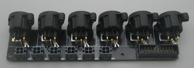
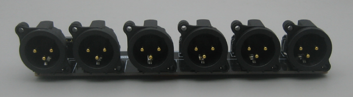
Neheb,
This looks great.
I am considering a DLP project. If i need a couple of these boards, do you have extra boards that you could sell?
Also do you know of molex to molex cables to connect this board to DLCP analog outputs?
- Home
- Source & Line
- Digital Line Level
- Hypex DSP module(s)