I have almost finished the build as described at:
Amplifier End by Andrea Ciuffoli
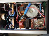
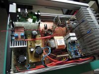
The two pictures enclosed are a preview of one channel. All voltages in the power supply are tested.
Before turn on I would like to test the tube stage first. In order to do so, I will terminate the two secundaries of the interstage transformer with a resistor of 1k each. Can someone please confirm this is ok?
A next question is about setting the bias of the mosfets. The instruction of Andrea reads: “Before to connect the mosfets set the trimmer to have about 1.8V DC on 470ohm resistors and after the power on increase both trimmers until the correct bias is set and turn only one trimmer to get zero DC voltage on output terminals.” However the preceding warning is: “please do not touch with multimeter the mosfet gate after power on because this operation will destroy the mosfets.”
I assume the procedure is to connect the leads of the multimeter before power turn on. Connect not on the gate itself, but before the gate resistor. Can someone please confirm this?
Amplifier End by Andrea Ciuffoli
The two pictures enclosed are a preview of one channel. All voltages in the power supply are tested.
Before turn on I would like to test the tube stage first. In order to do so, I will terminate the two secundaries of the interstage transformer with a resistor of 1k each. Can someone please confirm this is ok?
A next question is about setting the bias of the mosfets. The instruction of Andrea reads: “Before to connect the mosfets set the trimmer to have about 1.8V DC on 470ohm resistors and after the power on increase both trimmers until the correct bias is set and turn only one trimmer to get zero DC voltage on output terminals.” However the preceding warning is: “please do not touch with multimeter the mosfet gate after power on because this operation will destroy the mosfets.”
I assume the procedure is to connect the leads of the multimeter before power turn on. Connect not on the gate itself, but before the gate resistor. Can someone please confirm this?
Attachments
Hello to all,
frankly I'm a little surprised that there are problems in the implementation of this amplifier.
The schematic is very simple but like every audio realization you must create a good layout otherwise you will create many problems.
One person told me that his Hybrid Amplifier Circlotron have an oscillation and he had to add capacitors in various points to stop the phenomenon.
Obviously an amplifier without feedback will have oscillation only if you wrong the layout.
I add many photos on my projects to give many information about the layout to follow.
I repeat that the layout into an audio amplifier is very important and it is not possibile follow an electric layout.
The layout must be very linear from input to output without signal and ground loop.
The most delicate part of this project are the mosfet that you can break easily if you touch the gate with the multimeter.
Before switch-on verify all the ground are connected, input ground, tube ground, bias ground and output stage ground.
The best method for the initial setup is leave disconnected the mosfet (all pins) after:
1) turn on filaments of vacuum tubes and verify the light inside
2) turn on anodic power supply and verify voltage on anode about 160-180V and catode about 1.36V (20mA * 68ohm)
3) verify bias voltage and set all trimmer for 1.8V DC on 470ohm
4) turn on output stage power supply and verify the voltage about 40-50VDC is ok (still no mosfet connected)
5) switch-off all power supply
6) discharge the output stage power supply capacitors with 1Kohm 5W resistor
7) with all power-off verify bias voltage is zero and output stage power supply capacitors is zero
8) finally solder all the mosfet pins
9) switch-on al the power supply
Last edited:
The voltages of the power supply itself are ok. The anodic voltage after regulation is exactly 160V (B+). Instead of the D3A the E280F is used which should be a drop in replacement.
Only the tube stage is tested with a variac (mosfets not connected and not powered). The two secundaries of the interstage transformer were each terminated by a 47K resistor for this test.
I measured the current through the stage directly through a multimeter in mA setting. The variac was slowly increased untill 20 mA through the interstage transformer at 160V is reached. The original value of 68 ohm should give about 1,4V (measured from ground to cathode). However, this value proved to be too low to meet the 20 mA at 160V. Eventually the value of 68 ohm had to be increased to 1K8. In this case the 160V at 20 mA was met, but then the voltage at the cathode is almost 35V. According to the datasheet the load line now is way off from where it should be.
Can someone please tell me what I am missing?
I am looking for a commercial power amp or integrated amp where this topology is inside.Hybrid better than SE vacuum tube amp. ?
Look my simple design in testing phase
Hybrid Amplifier by Andrea Ciuffoli