So i could mabey use BD139 and BD140 for the drivers (like i did on those amp boards for a while) at the moment? they can take the voltage the amp will be running at and have fairly flat gain vs current curve and i have a load of them here still that i could use to get it up and running and for some testing? Then all i have to do is find something i have that would be ok to use for the bias transistor... and order the transistors for the first SS stage.. and put it all togetehr in a way that it dosnt blow up..
many thanks,
Owen
many thanks,
Owen
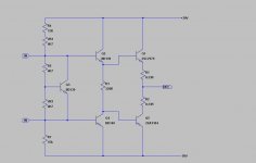
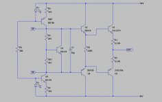
ok, i have thrown together a rough schematic of the output stage, havent included any of the extra resistors for protection yet, Not sure the bias circuit is correct? Anything i have missed out? i just put it togetehr quickley useing the original schematic as a guide.
many thanks,
Owen
many thanks,
Owen
Attachments
Hi Owen,
That will work as a start. You will find that your bias current will vary as the supply voltage. You need to add about 10uF across the bias transistor from C to E. A couple of current sources would increase the impedance (very much desired) and reduce the influence from the rails.
For DC offset, why not use a couple high value resistors to a pot between a couple references - say +- 5 V ish? That will eliminate the interaction between DC offset and bias current.
-Chris
DoomPixie said:ok, i have thrown together a rough schematic of the output stage, havent included any of the extra resistors for protection yet, Not sure the bias circuit is correct? Anything i have missed out?
The lower transistors Q4 and Q5 are upside down...you must put the emitter , where now is the collector..and the oposite.

anatech said:Cool Tube_Dude,
I didn't even see that until you mentioned it. Interesting how the mind works as I saw what I expected and not what was there.
That's because I was using my reading glasses...
Hi Owen,
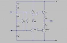
Just invert what you have for the positive supply using a BD139 or use 2SC2240, 2SA970 for the positive (better performance). You could increase the standing current to 2mA without worrying about dissipation.
You missed the added stage to increase the input impedance to make this a triple darlington. It would use 2SC2240 and 2SA970 as well. Try it with and without. The bias setting will be very different as you have around 1.2V more and much less current with the added stage.
-Chris
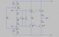
I have inverted the CSS on the negative rail, I Will try it without the added stage first and then probably add it in after my 2SC2240 and 2SA970's arrive.. But BD139 and BD140's will bo ok in all these positions for initial testing?
What value shoukld R6 and R8 be? i expect they should be something like 22K :S
Also does R3 look correct at 220Ohm?
What should i do to help avoid it blowing up? i will fuse the + and - supplie's with fairly low value fuses and i will run a 60Watt light bulb in series with the Power transformer, anythign else i should do?
Many Thanks,
Owen
Attachments

Hi Owen,
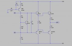
Put a resistor in series with VR1 to set the max current level and expand the useable range on the pot.
Combine R6 and R8 into one resistor between the two points. A 30K 1/2W would work but will dissipate close to 1/4W, I'd use a 1W. You can tack a pair of 15K 1/2 W in series. This avoids an unneeded ground connection and is easier to lay out.
Use a variac and monitor emitter currents as you bring it up. You may need to adjust the bias component values some. A light bulb may work, use a 25W bulb to start. I use a variac so I'm guessing here.
-Chris
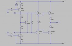
Ok, i added the resistor, i'm not sure what sort of value i should be useing here but i guess that a high value is going to be safer (limit the bias current more)? Anyway, here are the updated schematics, Will start hooking it up on my breadboard so i can see if it works. Will there be problems because i am building it on a breadboard to test? Should i mabey wait untill i have some stripboard or something?
Many Thanks,
Owen
Many Thanks,
Owen
Attachments
DoomPixie said:Ok, i added the resistor, i'm not sure what sort of value i should be useing here but i guess that a high value is going to be safer (limit the bias current more)? Anyway, here are the updated schematics, Will start hooking it up on my breadboard so i can see if it works. Will there be problems because i am building it on a breadboard to test? Should i mabey wait untill i have some stripboard or something?
Many Thanks,
Owen
This design will results large DC offset. You have to use DC servo to keep it within safe value.
sajti
DoomPixie said:hey sajti,
Could you please explain why it will result in a large DC offset? mabey i can work out a way arround it then? thanks for letting me know before i build it though.
many thanks,
Owen
The problem is, that this circuit is very sensitive for the current of the ccs. If there is any difference between them, that will results very large offset, due the low bias current flow into the drivers.
This offset will depended by the temperature as well. So this circuit simply doesn't work without servo.
sajti
- Status
- This old topic is closed. If you want to reopen this topic, contact a moderator using the "Report Post" button.
- Home
- Amplifiers
- Tubes / Valves
- Hybrid amplifier help...