HI Zen Mod, you mean the output stage of BA-3? isn't it the same effect increasing source resistor or putting in a drain resistor and not changing the source resistor.....? I am bit ashamed not to know this....

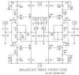
look at attached Papa's (witty drawn) schematic ;
( nobody can' say that he don't have unexpected sense of humor
 )
)you can decrease gain in two , or in both ways :
- put appropriate sized resistor between drains of Q1 and Q101 and same value resistor between drains of Q2 and Q102
- put appropriate sized resistor between sources of Q3 and Q103 and same value resistor between drains of Q4 and Q104
dunno which way is more effective ; I'm always lazy to simulate anything , and my head is now even fuzzier than usual ; probably lack of sleep ....
Attachments
O.k. I understand, it is the same idea you showed with changing the gain of the differential pair of j74......
That's a good tip! I will try first solution and I will take a 5k pot for the beginning.
the sense is I can partially combine + and - signal to cancel a certain amount, correct.....?
But isn't this a kind of feedback?
That's a good tip! I will try first solution and I will take a 5k pot for the beginning.
the sense is I can partially combine + and - signal to cancel a certain amount, correct.....?
But isn't this a kind of feedback?
Last edited:
well
when walking on the street , on nice lazy evening , you twist your neck to see some German beauty ......... do you call that - feedback ?
everything is feedback ; even Papa's 200R resistor from one half to another is sort of feedback
edit:
don't use pot - it's hard to balance lower and upper
use fixed resistors
you can start from 1k (even 470R) and go down from that
Last edited:
contemplating about BBA3 FE:
now - you have famous resistor between sources
sort of current sharing SUSY setup.
you forgot , and didn't asked , that you can also implement resistors between upper drains and , of same value , one between lower drains ?
I must admit, that like Generg, I do not understand how this affects thing. This is tricky situation of understanding gain, Q-point and degeneration and how they work together?
sort of current sharing SUSY setup.
nope ; it isn't SUSY anymore ; heart of SUSY is differential feedback around stages (looping them , if that's right verb) ; this is similar , but still more in a manner of degeneration /loading
it's called different , I think , but let Papa say what he have to say , when time comes . I'm pretty sure that he coined nice name for it
.....
I must admit, that like Generg, I do not understand how this affects thing. This is tricky situation of understanding gain, Q-point and degeneration and how they work together?
ho sez that I'm understanding it ?
Attachments
IF I wanted to use a Standby switch, Would rigging up a switch and LED/resistor in series with + and - rails do the trick. Switched one way, power to the board, the other power to LED, wich will keep the Cap bacnk charged. AM I way off and do you have any better suggestions?
Works like a charm on my Zv4 with 90mF/ch of caps. Requires a main power switch and On-On Standby/Play switch. The latter keeps the caps charged with a standby LED lit orange and in play mode turns blue and plays music. I also don't have to keep replacing 3A fuses every power-on. Initial power on (make sure PSU is ok) requires a bigger fuse. Let it soak for a few minutes then power off and change-out to specified fuse value
This gave me the idea. trying to avoid inrush of current on cap bank on turn on.
yeah - big deal - making thing complicetd than needed
use any soft start schematic , but instead of fixed resistors put same ohmic value NTCs ;
that way you don't need to calc RC constant , to avoid relay arcing ( there is no universal soft start - each different cap bank/xformer combo need different amount of resistance) , and that way you have real soft start
best of both worlds , so to speak
besides - putting switch on heavy load side is big nono , in my book
everything , published by Nelson , is adequate for 90% of DIY-ers .
last 10% are insane , and always think that they can better
1% of them really knows how to make that better , but not thanks to fact that Nelson doesn't know how to make better ....
blahblah
conclusion - it's always safe bet , to make things exactly as Nelson does .
last 10% are insane , and always think that they can better
1% of them really knows how to make that better , but not thanks to fact that Nelson doesn't know how to make better ....
blahblah
conclusion - it's always safe bet , to make things exactly as Nelson does .
Attachments
I just fired up seconf output stage and have 7 out of 8 fets working. One is not conducting current at all, even with appropriate Vgs and Vds. Its parallel brother is biased slightly higher than all the other properly working fets at about .9A vs .75a for the others. Whats going on with this fet?

- Status
- This old topic is closed. If you want to reopen this topic, contact a moderator using the "Report Post" button.
- Home
- Amplifiers
- Pass Labs
- Humble Beginnings:D