Readjusting to -0.405v.
Flat response, no metal shields, reading is: -91.5 dB.
Engaging 80 kHz. Filter reading is: -93.5 dB.
Steven
Again to review working on Unit #2 which showed about 11% to 12% distortion when it arrived here just over a week ago. Main problem found - open Jfet Q2.
Currently U1 was replaced with a socket and an LT1468, R30 was replaced with a 25 turn trimpot and the readings are seen quoted above (with original part for U3).
Tonight the two mica caps 510 pf and 27 pf were unsoldered, and U3 was unsoldered and replaced with a socket. A National LME48710NA from China was put in first in place of the original selected part from 1980's.
Test #1
Results: 1 kHz. 2 Volts,
TP8. -.471 v.
Flat -88.5 dB
80 kHz. -91.0 dB
A second sample of the LME49710NA was put in, it did a little better, by about 1 to 1.5 dB.
TP8. -.471v.
Flat -90.2 dB
80 kHz. -92.2 dB
Test #2
U1 was replaced by an AD747ANZ, U3 remains the 2nd LME49710NA
TP8 -.480 v.
Flat. -89.5 dB
80 kHz. -91.2 dB
Test #3
U1 was replaced by an NXP5534P, U3 remains the 2nd LME49710NA
Osc did not function. ???
Test #4
U1 was replaced by the LT1468 again, U3 remains the 2nd LME49710NA
TP8 -.480 v.
Flat. -90.2 dB
80 kHz. -92.2 dB
Looks like the original parts are difficult to improve upon...
Comments?
Steven
Last edited:
Hi Steven,
You're approaching factory specified performance, so things are more challenging. So a few points to ponder:
It's not entirely clear if your reported performance is is being limited by residual distortion or by random noise within the instrument. So I recommend performing the residual noise test mentioned earlier, Section 4-25 in the manual. Several benefits here---the oscillator is not involved in the test, good noise performance is necessary in any event for superlative distortion readings, the test helps rule out at least one unknown, etc. Also, noise floor benchmarks are good data to have if you eventually pursue quieter opamps in the analyzer section--- you'll be able to confirm noise reduction as you introduce replacement devices.
A couple of times you've mentioned testing at 2V signal levels. I believe HP mentions testing at somewhat higher amplitudes and the larger levels might result in modestly improved numbers. (Ratio between 2V and 3V is 3.5dB!)
Study Sections 4-22 and 5-17. You may not have all the equipment HP suggests, but scoping the monitor output while adjusting A4R16 and A4R43 may be insightful. Triggering the scope with the input signal may be helpful in seeing the distortion residuals, but make sure that connecting the scope to the input doesn't introduce new artifacts.
Good luck.
Saturday turns out to be a good day!
Not sure if the 339A voltmeter is reading accurate, but on the 3 Volt range the meter reads 2.2 volts when fully cranked, so while reading on the 0 to 3.2 volt scale, I get 2.00 v, my Fluke 79 Series II reads ACV at: 6.38 volts and 991.2 Hz., Not exactly the same. Have I been reading the wrong scale on the 339A? 2.00V also would be .632 on the 0 -1 scale... Times ten that would agree with the Fluke?
With the 339A reading at 2.00 Volts, my prior readings were at the level of -88.5 dB Flat, I believe, when I last reported on this set, which has an LT1468CN8 with pin #8 removed, for U1 and an LME49710NA for U3, a 25 turn pot for R30, and two mica caps removed from the board at U1. No other changes or modifications from stock as it left the factory. No shields at A1 are installed.
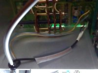
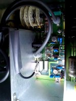
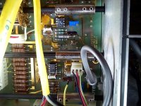
Today I spent some time adjusting Unit #2's A4 board, pots A4R16 and A4R43, this was able to get me down another few dB to about -90.5 dB Flat. I also tried moving a black shielded cable that runs parallel to and with some of the RCA terminated cables and also the blue and yellow wires that run around close to the A4 board... Somewhat interesting! Taping the black shielded wire to the aluminum shield, in two places, and moving the blue/yellow wire pairs down to the shields also gained about another -1.5 dB so now with no other component changes, after a while, it nulls at -92.0 dB Flat and -96.2 dB with the 80 kHz. Filter in!
Given that -96.2 dB reading is difficult to duplicate, coming in at -94.5 dB a bit later, and closing in on -95.0 dB with some jumping around, maybe microwave phone signals in the area are buzzing in and out, it's not a shielded room over here!
I believe that is actually quite good - better than the revised factory specs in the manual changes section.
Oh, Happy Day.") .
.
Now let's see what is going on with Unit #3.
Steven
Hi Steven,
You're approaching factory specified performance, so things are more challenging. So a few points to ponder:
It's not entirely clear if your reported performance is is being limited by residual distortion or by random noise...
A couple of times you've mentioned testing at 2V signal levels. I believe HP mentions testing at somewhat higher amplitudes and the larger levels might result in modestly improved numbers. (Ratio between 2V and 3V is 3.5dB!)
Study Sections 4-22 and 5-17. You may not have all the equipment HP suggests, but scoping the monitor output while adjusting A4R16 and A4R43 may be insightful.
Good luck.
Not sure if the 339A voltmeter is reading accurate, but on the 3 Volt range the meter reads 2.2 volts when fully cranked, so while reading on the 0 to 3.2 volt scale, I get 2.00 v, my Fluke 79 Series II reads ACV at: 6.38 volts and 991.2 Hz., Not exactly the same. Have I been reading the wrong scale on the 339A? 2.00V also would be .632 on the 0 -1 scale... Times ten that would agree with the Fluke?
With the 339A reading at 2.00 Volts, my prior readings were at the level of -88.5 dB Flat, I believe, when I last reported on this set, which has an LT1468CN8 with pin #8 removed, for U1 and an LME49710NA for U3, a 25 turn pot for R30, and two mica caps removed from the board at U1. No other changes or modifications from stock as it left the factory. No shields at A1 are installed.
Today I spent some time adjusting Unit #2's A4 board, pots A4R16 and A4R43, this was able to get me down another few dB to about -90.5 dB Flat. I also tried moving a black shielded cable that runs parallel to and with some of the RCA terminated cables and also the blue and yellow wires that run around close to the A4 board... Somewhat interesting! Taping the black shielded wire to the aluminum shield, in two places, and moving the blue/yellow wire pairs down to the shields also gained about another -1.5 dB so now with no other component changes, after a while, it nulls at -92.0 dB Flat and -96.2 dB with the 80 kHz. Filter in!
Given that -96.2 dB reading is difficult to duplicate, coming in at -94.5 dB a bit later, and closing in on -95.0 dB with some jumping around, maybe microwave phone signals in the area are buzzing in and out, it's not a shielded room over here!
I believe that is actually quite good - better than the revised factory specs in the manual changes section.
Oh, Happy Day.
. Now let's see what is going on with Unit #3.
Steven
Attachments
 That's great news! Well done.
Not sure what to make of your oscillator amplitude readings. I'm inclined to believe the Fluke because your earlier measrements showed correct oscillator amplitude at the test point. A peek with your scope would be "a second opinion" on amplitude. Comparison with unit #3 may be helpful in debugging amplitude reading.
Good luck with #3.
Checking and comparing Oscillator amplitude readings, given that both HP-339A sets are showing a reported Oscillator output reading of 2.0 Volts on the 0 to 3.2 Volt scale (I was using the correct scale) while the Fluke 79 Meter at the bananna output jack's gave very different readings.
For Unit #2, the Fluke shows a reading of 6.38 Volts AC; on Unit #3 it indicates a very accurate 2.002 Volts AC. I tend to think either some components have failed, or that someone severely mis-calibrated the settings for the voltmeter (much more likely) in Unit #2. Either way I will have to attempt to reset the Unit #2 internal voltmeter adjustments, until it matches Unit #3 and (hopefully!) also agrees with the Fluke Meter. Then I guess the distortion numbers will be a bit worse, and so I will need to restate them all over again.
A techs' work is never done,
Steven
The 1:3 ratio suggests the range knob is on incorrectly. Check that it goes to the correct end stops first.
Having multiples of instruments is great when they all work but multiplies the maintenance burden. I have 3 Boonton analyzers that all have issues. 3 ESI videobridges with issues and 3 Tek 7854 scopes that work but with some issues. It has become clear that this is not the best strategy. It was to dump the failed unit and switch to a healthy one however I'm not capable of ditching something that almost works.
Having multiples of instruments is great when they all work but multiplies the maintenance burden. I have 3 Boonton analyzers that all have issues. 3 ESI videobridges with issues and 3 Tek 7854 scopes that work but with some issues. It has become clear that this is not the best strategy. It was to dump the failed unit and switch to a healthy one however I'm not capable of ditching something that almost works.
... however I'm not capable of ditching something that almost works.
Fortunately for me, my wife seems to subscribe to the same philosophy.
I also follow the same philosophy. I try to have a spare for any instrument that is critical. Of course, hte RTX 6001 doesn't have a spare waiting in the wings.
Having a spare HP 339A has saved my bacon in the past. More things to keep running, but at least that policy makes it possible to carry on with what you're doing and deal with the failed equipment later.
-Chris
Having a spare HP 339A has saved my bacon in the past. More things to keep running, but at least that policy makes it possible to carry on with what you're doing and deal with the failed equipment later.
Yes, absolutely! That makes more sense than a mystery failure that reduces the output level by that much.The 1:3 ratio suggests the range knob is on incorrectly.
-Chris
PHP:
The 1:3 ratio suggests the range knob is on incorrectly. Check that it goes to the correct end stops first.
Hi guys,
After reading through the mods section abridged by Sync, I noted that for the 1468 at U1 it did state removal of CR7 and CR8 as well as C45 and C48, the mica caps, for the best overall performance. I left the diodes on the board, while not connected to pin 8, or really anything else, except +15 Volts, they are essentially disconnected, except for stray capacitance coupling. I doubt that they still may affect the circuit in a meaningful way.
Last night I made a few more adjustments here and there, tightened up the setscrews on the switch couplings, and made up a shielded 1k ohm load plug, that I wrapped in clear plastic tape, then copper tape. Then covered it with duct tape. I then made one final adjust of the null pots on A4, and installed the A1 shields, and the top and bottom covers.
I was also thinking about replacing R51 on the Q2 Jfet, in each set, with a 1k resistor in series with a 2k 25 turn trimpot, and also replacing the 10k Output Level potentiometers, with a modern 10 turn wirewound pot, but decided I could always do those two things in the future if the results are not so hot. While I have more 2k 25 turn trimpots on order, I have yet to order any 10k 10 turn Output Level type pots.
At this time, both of the HP339A AC Voltmeters agree with my Fluke's ACV readings within about 1/2 %.
However, things are looking quite good.
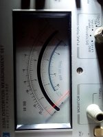
Unit #2, formerly 12% THD some ten days back, on the Residual Noise test reads -103.0 dB. That is below the scale starting point and over 10dB better than the spec. The 1 kHz. distortion, with the 80 kHz. filter on, at a signal level of 3 Volts came in at -98.0 dB, or around 0.0013% again way better than the spec. The unselected combo of an LT1468 at U1 followed by an LME49710 at U3, apparently gains a couple of dB over the selected HA2625 parts of 35 years ago, but realistically it is an improvement of about -2.5 dB to -3.0 dB.
Unit #3 my old set, with all the original 1983 IC's still installed, clocked -102.5 dB on Residual Noise, and THD down at -96.5 dB or 0.0015%. There is some jitter, and the meter does move down to -97.0 dB back and forth continually, but -96.5 is still a pretty respectful reading. This set was just slightly worse than spec some five years back, when it would come in at 0.0020% to 0.0022%, but I had never adjusted the null trimpots on A4 previously, that I remember.
At TP1 both sets show about 6.68 Volts, +/- just a shade under 20 V. p-p.
So both are quite in the green.
Good enough!
My thanks to all who helped, commented, and made suggestions.
Steven
The photo is Unit #2 Residual Noise at -103 dB.
Attachments
Last edited:
My thanks to all who helped, commented, and made suggestions.
THx -RNMarsh
Have not read some of these last posts before. Steven, glad you got everything going and going well at that. Now when I get my QA40x working again...I want to redo some of those old mods I removed from my 339A. Eventually RN Marsh saved me from the waterboarding torture I had undergone, AND got the 339A going again.The point of the modding/hotrodding these is similar to that of hotrodding cars or anything really. Take it in small steps at a time, measure the results as you go along. While all the little steps might be a -.5dB THD improvement, just as there might be a 10 HP improvement in a car... ...ALL those little improvements make for a BIG improvement when they are all completed successfully. It's all that little stuff that adds up to a big improvement. Now, for that QA400 waterboarding I need to stop and get it running again on the Dell laptop.
Cheers,
Cheers,
Last edited:
Does anyone have an actual HP-printed HP339A service manual who could scan the parts list, Table 6.3?
My manual is downloaded from the web and is perfectly adequate for 95% of its content. But the parts list imaging varies from marginal to indecipherable.
Many thanks to anyone who can help me out.
My manual is downloaded from the web and is perfectly adequate for 95% of its content. But the parts list imaging varies from marginal to indecipherable.
Many thanks to anyone who can help me out.
I do, But the printed font HP used for computer generated parts list is low quality. Typical of most their service PL. Their emphasis is geared more towards serial number PL updates being accurate and easily tracked than 'readable'.
Why your PDF is hard to read.
It can be error prone if you don.t have updated changes for your production/serial number. What is your Serial number
PM me
Why your PDF is hard to read.
It can be error prone if you don.t have updated changes for your production/serial number. What is your Serial number
PM me
- Home
- Design & Build
- Equipment & Tools
- HP339A distortion analyser