Can you check the ripple voltage Vpp at TP3 on your Oscope?
The operating level dc reference is set at the inputs of U2A. Mainly R34 - R35 and the rail voltage. This sets the proportional control zero for the integrator and ultimately the operating level of the oscillator. R30 sets the Q for the Jfet.
I don't think I ever did publish a complete set of schematics for my SVO. I can put them on drop box for you if you wish to study them.
By the time I post results for the design, no one seemed to be interested. Too caught up in other discussion at the time.
The reason the SVO won't shut down from a clipping level is because that is far out from multiplier authority. I can force it other ways but not from the multiplier. The oscillator was deigned to operate around 3Vrms.
And yes it would be too far off topic to discus it here.
Why don't you PM me if you are still interested.
I rather discus this through email correspondence since it was discuses in the low distortion oscillator thread but not thoroughly in detail.
Non-hash-thingie: me too.
It if helps here is the link again:
HP339a Modification Summary
Many of the links in that don't work any longer.
The information is still correct.")
Cheers,
It if helps here is the link again:
HP339a Modification Summary
Many of the links in that don't work any longer.
The information is still correct.
Cheers,
A few days later, and
An Update.
I thought I would give the 339a set a rest, so tonight, after midnight, I pulled out set #3. This one has a full set of knobs and generally is in the best cosmetic condition of the three units. Had this one over twenty years, and it's Oscillator just stopped working after being unplugged since about four years back.
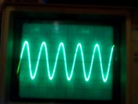
The PS measured +15.00 and -15.01, so no problem there. Readings on TP8 were kind of all over the place. Pressing hard on TP8 gave me a waveform occasionally. What is nearby? R30 and U1! I think R30 may be problematic. Pressing on the center adjust, I could make the waveform come and go. On the reverse of the board, it looks like U1 had been replaced at some time in the past, as the only part having rosin present on its pins.
So I dug through my 2K trimpots, found another 25 turn unit, that was over 2k between the outer pins, and replaced R30. This 339a is now working well without jumping voltages or waveforms. But I suspect something is noisy. At 1kHz. And 2 Volts, the current level of distortion when flat is hovering around -82.8 dB, engaging the 80 kHz. filter drops that down to about -93.8 dB with a bit of jitter going between -93.5 and -94.2 dB. None of the internal shields is installed for these readings, but I don't see much improvement when they are in place anyway.
That wideband noise, I wonder if I should install a socket and an LT1468 for U1? There was not much difference between "flat" and 80 kHz. bandwidth limited readings on the other set, with the 1468 installed, certainly not close to 12 dB.! The waveform is off the center tap of R30.
Well 5 AM, that's it for me, gotta get some more sleep.
Comments?
Steven
An Update.
I thought I would give the 339a set a rest, so tonight, after midnight, I pulled out set #3. This one has a full set of knobs and generally is in the best cosmetic condition of the three units. Had this one over twenty years, and it's Oscillator just stopped working after being unplugged since about four years back.
The PS measured +15.00 and -15.01, so no problem there. Readings on TP8 were kind of all over the place. Pressing hard on TP8 gave me a waveform occasionally. What is nearby? R30 and U1! I think R30 may be problematic. Pressing on the center adjust, I could make the waveform come and go. On the reverse of the board, it looks like U1 had been replaced at some time in the past, as the only part having rosin present on its pins.
So I dug through my 2K trimpots, found another 25 turn unit, that was over 2k between the outer pins, and replaced R30. This 339a is now working well without jumping voltages or waveforms. But I suspect something is noisy. At 1kHz. And 2 Volts, the current level of distortion when flat is hovering around -82.8 dB, engaging the 80 kHz. filter drops that down to about -93.8 dB with a bit of jitter going between -93.5 and -94.2 dB. None of the internal shields is installed for these readings, but I don't see much improvement when they are in place anyway.
That wideband noise, I wonder if I should install a socket and an LT1468 for U1? There was not much difference between "flat" and 80 kHz. bandwidth limited readings on the other set, with the 1468 installed, certainly not close to 12 dB.! The waveform is off the center tap of R30.
Well 5 AM, that's it for me, gotta get some more sleep.
Comments?
Steven
Attachments
Last edited:
Hi Steven and all HP339A "hot rod" enthusiasts,
I highly applaud anyone anyone attempting to improve the HP339A.
That said, I also strongly recommend first restoring the instrument to factory specified performance before beginning modifications. Not doing so risks confounding the confusion when results are disappointing--- you don't whether to suspect the mod or the original defect which may be entirely unrelated and undiscovered, perhaps even further obscured. To the extent possible, install modifications one at a time and confirm equal or improved performance before installing the next mod. Good luck to all!
Happy USA Independence Day!
Hi Steven,
Wow, THREE HP-339A! I'm envious.
Re your suspected noise problem with unit 3, some scatter shot questions. Am I correct in inferring the distortion products are buried in the noise as seen on a 'scope connected to the monitor output? With -80dB residual, I think residual distortion would be visible in the monitor output; if buried in noise, analyzer noise floor may excessive. Some checks of the analyzer noise floor in the test section may lend insight. And of course a trip through the adjustment section if you haven't already done that.
How's unit 2? I was fantasizing that readjusting the TP8 voltage might do wonders for it.
Unit 1 has the broken switch wafer? What's the state of the other half of the unit? With multiple instruments, you can do a lot of experiments with an oscillator in one feeding an analyzer in another and localize faulty instrument sections, compare performance, etc. I'm starting to ramble...
Have a great 4th!
One of the issues noted with the 339A is elevated noise from the filters. Some blamed the Sallen Key filter topology for the increased noise. However I pointed out that the Shibasoku 725B/C/D also use Sallen Key and they do not exibit this problem. The only difference I can see is the passive values. the 725 filters use much lower resistor values. It also depends on if these filter are tuned for Butterworth, Chebyshev, Bessel etc.
In high order filters particularly with Chebyshev and the like there can be a sharp increase of noise gain near the fc.
The Shibasoku 725D has an option for a 9th order brick wall filter. Although the signal gain is quite flat there is a noise gain at fc of about 35dB.
In high order filters particularly with Chebyshev and the like there can be a sharp increase of noise gain near the fc.
The Shibasoku 725D has an option for a 9th order brick wall filter. Although the signal gain is quite flat there is a noise gain at fc of about 35dB.
Hi Steven,
Wow, THREE HP-339A! I'm envious.
How's unit 2? I was fantasizing that readjusting the TP8 voltage might do wonders for it.
Hi Techs,
Interestingly, on Unit #2 adjusting the TP8 voltage from +.4v. to -.4v did not seem to have much effect.
I still suspect Unit 3 may have a noisy or oscillating IC (U1 or U3) maybe?
Unit #1 with the two or was it three switches with broken wafers, I removed Q2 from that set to put it into Unit #2. after that J-fet was found to be open. Of course, some of the Unit #3 problems were just solved by replacing R30.
However, I can experiment, as I do have a number of AMBER 3501 and 3501A sets, however, they are lower on my list than the HP339a's. At least two of the AMBER sets still smoke (bad partially shorting tantalum bypass caps) and some burnt / melted adjustment pots (positioned too close to tantalum caps - that actually caught fire!): So, I don't think any of these sets really meets their factory specs at this time (one may be close).
One problem that doesn't seem to be addressed in the OP/SERVICE Manual directly on all of these AMBER sets is the downward deflection of the meter, below "0", an electrical offset, under many conditions, not a mechanical problem. I think all suffer from that, maybe a full calibration will solve it, maybe it's just a DC offset that is way off, or another Tantalum cap problem?
Eventually, if I live long enough, I would like to get the AMBER sets working too
.Getting back to Unit #2...
Oops, can't find my double b to double b cable, have to find that before I can take any readings. Well goodnight, maybe tomorrow for Unit #2.
Steven
Hi Techs,
Interestingly, on Unit #2 adjusting the TP8 voltage from +.4v. to -.4v did not seem to have much effect.
Getting back to Unit #2...
OK found the cable (on unit #3 of course).
First should the set be on 10 Hz. Or 1kHz. For adjusting R30 the manual is not specific if I recall?
Assuming 1 Khz. 2.0 volts output, when tuned to 1 k voltages are different than at 10 Hz. So it does seem to jump from time to time. Readjusting to -0.405v.
Flat response, no metal shields, reading is: -91.5 dB.
Engaging 80 kHz. Filter reading is: -93.5 dB.
Like I stated, Unit #3 when set flat (-82.3 dB) seems to be in the right area, but noisy!
Comments?
Steven
Readjusting to -0.405v.
Flat response, no metal shields, reading is: -91.5 dB.
Engaging 80 kHz. Filter reading is: -93.5 dB.
Last point there are a few components that attach to pin 8 on the LT1468, but that pin has been removed, they also connect to the output of the IC and to the Jfet, a nice mica cap or two, or three, two small diodes, another resistor, or two, I read most of these should be removed, does that include the two diodes too?
Comments?
Steven
Attachments
Last edited:
I think the mod procedure mentions removing these components. With U1 pin 8 removed, I doubt the presence of these parts will have any effect, but removing C45 and C48 will eliminate any possibility.
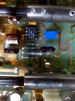
I see the replaced U1 opamp. Are there any other upgrades already in place?
Noise issues can be a challenge. Would you try performing the residual noise test--- Section 4-25 in service manual? Few us have the shielded hoods prescribed in paragraph b. Use a short wire (e.g. a resistor lead) in lieu of the 1K resistor to short the input. If the spec isn't met with ease, install shields to ensure their absence isn't involved. We do live in a rich EMI environment these days. If the noise spec fails, look at monitor output with a scope for possible insight.
Good luck.
I see the replaced U1 opamp. Are there any other upgrades already in place?
Noise issues can be a challenge. Would you try performing the residual noise test--- Section 4-25 in service manual? Few us have the shielded hoods prescribed in paragraph b. Use a short wire (e.g. a resistor lead) in lieu of the 1K resistor to short the input. If the spec isn't met with ease, install shields to ensure their absence isn't involved. We do live in a rich EMI environment these days.
If the noise spec fails, look at monitor output with a scope for possible insight.Good luck.
Last edited:
- Home
- Design & Build
- Equipment & Tools
- HP339A distortion analyser