here is the original I did. see attached pict. Replace pot, changed C and R.... higher C value and high quality bipolar (105C) and 20 turn trimmer used to reduce 2H to min.The 339A has been working good since the repair a few weeks ago so I decided to tweak on it a bit more. <snip>
You should then get lower THD.

THx-RNMarsh
Last edited:
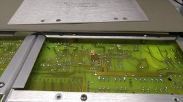
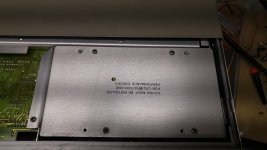
Today I installed the TL074 into the 339A oscillator (U2) and replaced R51 with a 10k multi turn potentiometer to complete the mods pioneered by you guys. I noticed that it would be easier to mount the R51 potentiometer to the backside of the oscillator PCB (pictures included). It sits perfectly in the space between the pcb and the cover. In so doing if you drill a hole through the upper oscillator cover you have quick access to this potentiometer to adjust the 2H. I put a dab of liquid nails glue on either side of the potentiometer to stabilize it to the pcb and drilled the hole in the cover. Now all I've got to do is slide the top cover back about 4" and I can adjust the 2H, if I leave the upper slide cover retention screw out then it only takes a couple of seconds to gain access to it without having to power down.
If you mount the potentiometer the other way to the front side of the PCB then you have to flip the 339A over and remove two panels to adjust the oscillator 2H, in other words its a PITA.
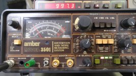
The good news is that these mods further improved on the 339A oscillators performance. The 339a measuring itself only showed a modest drop from .00065% to about .00062% THD. Yeah, its hard to tell that much of a difference with the 339, but it did drop some. However the 339A oscillator fed into the Amber 3501 showed a larger drop in distortion, going from .00047% to .00037% after 2H adjustment, about a 2dB improvement. I'm now sitting just shy of -108.5dB on the Amber. I don't know if I'm more impressed with the 339A oscillator or the Amber's ability to measure it. If I switch to 10kHz I'm showing about .00085% THD on the Amber without touching the 2H potentiometer on the 339A. Prior to setting it up for 1kHz it was about .00091% so even 10kHz improved, but is not optimal.
It seems I'm up against the wall with the 339A's analyzer, as its distortion measurement is not dropping much any longer even though the oscillator's showing definite improvement. I went back in and touched up the 339A nulling for the notch but it didn't improve the measurements of the 339A any further. I know some of you (RNMARSH, etc) have had their 339A reading well below the .0005% level.
If you mount the potentiometer the other way to the front side of the PCB then you have to flip the 339A over and remove two panels to adjust the oscillator 2H, in other words its a PITA.
The good news is that these mods further improved on the 339A oscillators performance. The 339a measuring itself only showed a modest drop from .00065% to about .00062% THD. Yeah, its hard to tell that much of a difference with the 339, but it did drop some. However the 339A oscillator fed into the Amber 3501 showed a larger drop in distortion, going from .00047% to .00037% after 2H adjustment, about a 2dB improvement. I'm now sitting just shy of -108.5dB on the Amber. I don't know if I'm more impressed with the 339A oscillator or the Amber's ability to measure it. If I switch to 10kHz I'm showing about .00085% THD on the Amber without touching the 2H potentiometer on the 339A. Prior to setting it up for 1kHz it was about .00091% so even 10kHz improved, but is not optimal.
It seems I'm up against the wall with the 339A's analyzer, as its distortion measurement is not dropping much any longer even though the oscillator's showing definite improvement. I went back in and touched up the 339A nulling for the notch but it didn't improve the measurements of the 339A any further. I know some of you (RNMARSH, etc) have had their 339A reading well below the .0005% level.
Attachments
Last edited:
For the most part .0005% and lower become limited by noise. A spectrum of the output will give you some insight. 3V seems to be the optimum for most analyzers for input SNR. Higher and the input attenuuator is a limiter. Lower and the input amp noise limits the lowest THD+N. I would look at the first stage of the input amp as a starting point to get the noise minimized. Then look at the residual harmonics in the output. Those may be from the nulling circuit. When you get that far there is lots to learn.
I’ve started work on making some improvements to my HP 339A, so that I can at least get it back to standard spec – or maybe slightly better for the oscillator. I know there has been a lot of work done by a number of people on this forum on repairing/upgrading the HP 339A and I have looked through most of this.
The HP339A (option1) was in working order, but the lowest distortion reading on the internal oscillator was .03% (1000Hz), as measured on the instrument itself. So I made the following changes based on the minimal upgrade suggested in the forum:
1. Replaced the power supply electrolytics (C304,C305,C306,C307). Supply voltages are low (around 14.2VDC for + and – rails) on both the oscillator and analyser supplies, but ripple seems OK (about 0.1mV)
2. Replaced the oscillator output pot (R3). This reduced distortion level to near .01% and allowed low output voltage (to around 2mV).
3. Substituted A1U1 (HA2-2625) with a LT1468 and removed associated compensation components (C44,C45,C48,CR7,CR8.,R29). C32, C47 left unchanged.
4. Replaced trimpot R30 with a 28 turn
5. Replaced R51 with a 3kohm trimpot
6. Replaced C30 with a 100uF bipolar
With 3v 1khz oscillator output, R30 adjusted for -0.40VDC at TP8 (as per manual).
Following these changes, the distortion (measured on the 339A, with 80kHz filter on) is:
100 Hz .0012%
1000 .0014
2000 .0018
5000 .0044
10kHz .0070
50kHz .33
Max frequency is 65kHz, but the output is a triangle wave at this point.
I don’t want to cover too much old ground, but would greatly appreciate some advice from those who have been there before on how to minimise the oscillator distortion, while maintaining the bandwidth. Perhaps change C32 or C47?
Sorry about the long post.
Thanks
Kerry
You should be able to get the oscillator out to 110kHz at 20Vpp at TP1. Can you test at TP1 and report? We need to know which section is slew limited.
I had one or two LT1468 which I suspected were not up to spec. But this was at a gain of 20 and slew limiting began around 350kHz.
Could be there is something wrong in the filters. Bad switch or cap.
Anything that could be causing unusually high stray capacitance around the op amp U1 could cause this. Sometimes a bad socket can cause this or other problems.
Hello David,
On TP1 there is 18.2Vpp up to around 5kHz when it starts to drop off towards 16 Vpp at the maximum frequency obtainable of 65kHz. The waveform becomes visibly distorted (triangular) above around 50 kHz. The lower (than 20Vpp) TP1 voltage may be because the supply voltage is lower than spec?
So it looks like the problem is in the U1 circuitry - and this is the only area I've made changes (apart from the power supply). Prior to making any changes the oscillator worked up to 109 kHz.
Looking back at earlier posts, some people have removed (or changed) C32 and C47, both of which I have left in. Could this be the problem?
Kerry
I don't recall C32 causing any frequency tuning issues. As far as I know this problem has never been reported before this. Whenever we make changes it a must to do a thorough inspection of the work. Check for shorts, solder bridges and if you used a socket try replacing it. It's possible the IC was damaged when putting it. These things, I'm sure, have stung all of us at one time or another.
The LT1468 is pretty much a drop-in replacement for this oscillator.
The LT1468 is pretty much a drop-in replacement for this oscillator.
Hello David
I've checked all my soldering (and recleaned the area) and can't see anything wrong. Replaced the LT1468 with another one - but this only reduced the maximum frequency to 60kHz. Also took out the IC socket and put in a new one - again no change.
Although very unlikely that this would be the problem, I removed C32 and C47. This had no effect on the frequency range.
At this point I'm wondering if there is a bad contact in one of the frequency range switches - in particular the 10/100/1k/10k. I did clean the contacts before starting the other work and don't remember there being any issue with their operation then. I'm reluctant to start fiddling with the switch too much unless I've eliminated everything else - they are fairly easy to damage, I think.
Kerry
A possibility in this case?
Kerry
I'm highly suspicious of this.
This IC is still in production. Can you not purchase it from an authorised dealer like Digikey?
Or better yet. Order samples from LT.
The LT1468 has a GBP of minimum 25Mhz. This is more than enough for 110kHz.
I've had this IC out 350kHz at a gain of 20.
Last edited:
Hello David, Chris
The LT1468 markings have on the top line the Linear Technologies logo, then "1626" and then "e3" (rotated 90 deg anti clockwise).
The second line has "LT1468" and the third "CN8".
From what I can find in the LT documentation, the pattern for their ICs is that the top line should contain 1468, followed by another number/letter(s) depending on the package type. The e3 indicates it is lead free.
So I think the LT1468s I have may be fakes.
I'll try now to find some genuine items - even if I have to use SOIC packages (more common) and an adapter.
Kerry

Hi Kerry.
We don't want to lead you down the wrong path with testing replacement.
You might end up with the same problem. But with out being able to dig into the unit ourselves it's very difficult to *****.
Like I said it's not a problem we've encountered before with these mods.
It's strange that a second op amp would reduce the max frequency further.
I know it driving your cost up doing this. But the question needs to be answered.
You could build up a basic amplifier on bread board and test the BW. But you would need a signal source that goes out to the Mhz.
The LT1468 has a complex compensation. The behavior changes between a gain of 30 - 36. The part behaves as a 90Mhz part. Below the said gain range it's 25Mhz part. That's why LT can advertise it as a 90MHz amplifier.
What exactly happens when you try to tune beyond 60-65kHz?
Maybe it just needs adjustment to the loop gain of the oscillator and jfet gate threshold. Have you tried this?
Replacing the amplifier will cause misalignment of both. The LT1468 is a lower GBP compared to the Harris part.
Last edited:
Thank you all for your help on this.
KC - the photo of your LT1468 is identical to mine, apart from the "1445" on the top line. Looking more closely at some of the info on Linear Technology date codes, I think the first 2 digits are year of manufacture ( not sure about the second 2 - perhaps week or batch number). So my "1626" code could well be valid.
In any event I have a couple more LT1468s on their way from Digikey, so I'll try those before delving further into the problem.
David - once I have a new LT1468 in place i'll look further at the question of oscillator loop gain and JFET gate threshold, as you suggest. I haven't done any adjustments to date (other than through R30).
On the issue of tuning beyond 60-65kHz, the frequency starts to drop below that indicated by the dial settings from about 20kHz. The limit of 60-65kHz is reached at about the 80kHz setting on the dials. Output voltage at TP1 drops from 18.2 to 16Vp-p over this range. The waveform becomes visibly distorted at about 50kHz and is triangular at the 60kHz maximum.
Kerry
It's sound like an amplifier with a BW or slew rate problem or both.
Hello David
Looks the problem was with this particular LT1468. I substituted a new LT1468 sourced from Digikey and the oscillator now seems to be operating normally. The new chip has the date code "1609" and a circular stamp adjacent to pin 1 (as does the photo posted by Chamberman). The old LT1468 (from Utsource) lacks this stamp.
The oscillator bandwidth now extends to 109kHz and distortion is below spec across the range. As measured by the HP 339A (3v output) it shows 0.0008% at 1000Hz (all filters on), 0.0012% at 10kHz, 0.0015% at 20kHz(80kHz filter on) and 0.0015% at 100kHz (no filters).
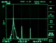
I don't have a computer based system to check these figures (or a better stand alone distortion analyser). However, I did attempt to use a HP 3561A to look at the 1kHz monitor output and adjust the trimpot substituted for R51 to minimise 2nd harmonic level. Screenshot attached.
I may be misinterpreting things, but it seems to show the 1kHz residual at -108dB, H2 at -48dB and H3 at -50dB.
I know others have been able to obtain much better performance from the HP 339a, but I think I'll probably leave mine as is, for the moment at least. It should be adequate for my main areas of interest - valve amplifiers and reel-to-reel recorders.
Thanks again to everyone for helping me out with this problem.
Kerry
Attachments
- Home
- Design & Build
- Equipment & Tools
- HP339A distortion analyser