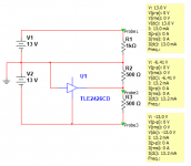
I never incorporated the regulators -- just used a bunch of single Lithium cells -- for the 3 voltages and ground -- here's a suggestion get one of Jan's "Silent Switchers" -- pretty small PCB and it can be powered by a wallwart to deliver +/-15V. for the "mid"negative voltage you can use a TLE2426 "rail splitter" which is a little TO-92 device and halves the voltage between two rails.
i have several HP403's -- one has a linear tech true rms converter in it.
i have several HP403's -- one has a linear tech true rms converter in it.
I'm trying this approach from Quantasylum:
http://https://quantasylum.com/blogs/news/simple-isolated-15v-split-rail
An evaluation board is available for the 2 LDOs - makes life simple but uses real estate. The SN6505 and transformer fit on a 45mm x 45mm proto board that can piggyback on the eval board.
Phil
http://https://quantasylum.com/blogs/news/simple-isolated-15v-split-rail
An evaluation board is available for the 2 LDOs - makes life simple but uses real estate. The SN6505 and transformer fit on a 45mm x 45mm proto board that can piggyback on the eval board.
Phil
Last edited:
Im sorry jackinnj, I misnterpreted your comments in your 2013 post. I thought you had actually built a regulator circuit when you mentioned the use a BUF634 artificial ground and LMXXXL regulators, etc. I like the idea of the rail splitter to generate the -6.5v supply.
Phil, that circuit idea is good. I had forgotten that a bipolar supply can be derived from a single ended transformer by using a half wave doubling rectifier. The transformer in the HP403B could therefore feed the rectifier in that circuit without using the SN6505.
I guess +/-15v is acceptable for the unit, as opposed to the +/-13v nominal.
Last edited:
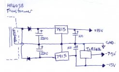
Forgot to add that the 2 filter caps would obviously need to be much bigger in value if using the HP's transformer output (at 60Hz) than whats used in the SN6505 inverter crcuit. So, the split rail rectifier / filter could then feed a 7815L and 7915L, with a rail spltter to generate the -7.5v, like jackinnj's idea of using a TLE2426.
Last edited:
There's a lot of good info on the TLE2426 with several schematics at Virtual Ground Circuits. There are some buffered versions there if you need more current from the -7.5 rail.
I did some rough calculations of the current draw from each supply. No worries about neeeding a buffer, as the -6.5v line draws less than 1 mA, and the +/-13v supply lines both draw less than 10mA.
There's a lot of good info on the TLE2426 with several schematics at Virtual Ground Circuits. There are some buffered versions there if you need more current from the -7.5 rail.
- Status
- This old topic is closed. If you want to reopen this topic, contact a moderator using the "Report Post" button.
- Home
- Design & Build
- Equipment & Tools
- HP 403B Volt / dB meter problem