JojoD818 said:What are the suitable values for R1 and R2 (Gain) resistors?
my favorite has been 20k/1k combo, part because I have lots of them. In addition, higher values in theory will cause more noise and higher DC offset. But I never experienced that in my trials.
JojoD818 said:I forgot something to ask.... what do I do with the E/S pin? Should I just connect it to the V+?
Regards,
JojoD
i just snapped off the pin. it does not need to be connected.

Hi all!
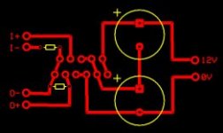
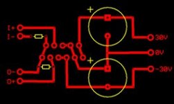
I'm new to diy audio stuff, and want to make my first simple chip amps, but I don't know if the schemantic I have is OK for my needs (I think I already blew 2 ICs with the previous I used). I'm using OPA 541/549. I'll be happy if you could look at these 2 test PCBs. Both were made for the OPA 549T, the first test circuit will be powered by a PC ATX power supply since I don't have a dual supply yet, the second by a dual one when I'll get a dual 30V toroid (and have the time to make the regulator etc.) Source will be my sound cards sub out, on the out is a 8ohm sub.
Thanks a lot,
dArk
Attachments
dArk said:Hi all!
I'm new to diy audio stuff, and want to make my first simple chip amps, but I don't know if the schemantic I have is OK for my needs (I think I already blew 2 ICs with the previous I used). I'm using OPA 541/549. I'll be happy if you could look at these 2 test PCBs. Both were made for the OPA 549T, the first test circuit will be powered by a PC ATX power supply since I don't have a dual supply yet, the second by a dual one when I'll get a dual 30V toroid (and have the time to make the regulator etc.) Source will be my sound cards sub out, on the out is a 8ohm sub.
Thanks a lot,
dArk
dArk said:and the second one:
Cant see anithing?!
till said:i used 10k and 100k
it depends on the gain you want and the input resistance you need. If you need more gain use 10k/200k, if you need more input resitance use 20k/200k and so on.
For NIGC (sch. above)
It's not going to efect the input impedance of the amp. but if you use 20k/220k and 22k from +In to gnd, you may expect a lot less DC offset at the output. The input impedance would depend on the 22k from +In to gnd only.
>It's not going to efect the input impedance of the amp. but if you use 20k/220k and 22k from +In to gnd, you may expect a lot less DC offset at the output. The input impedance would depend on the 22k from +In to gnd only.
Not such a biggee with these since they have jfet inputs
Not such a biggee with these since they have jfet inputs
hitsware,
You are correct. Still thinking about LM3875.
And by the way it makes OPA549 a very good candidate for this!
http://www.diyaudio.com/forums/showthread.php?postid=259500#post259500
You are correct. Still thinking about LM3875.
And by the way it makes OPA549 a very good candidate for this!
http://www.diyaudio.com/forums/showthread.php?postid=259500#post259500
Hmm... well, I posted the images too (the preview showed them as well) so I don't know why they aren't there. I uploaded them somewhere, so here are the 2 links:
http://xpro.etox.net/pcb1.jpg - the single supply one
http://xpro.etox.net/pcb2.jpg - the dual one
dArk
http://xpro.etox.net/pcb1.jpg - the single supply one
http://xpro.etox.net/pcb2.jpg - the dual one
dArk
Re: OPA541
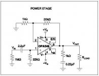
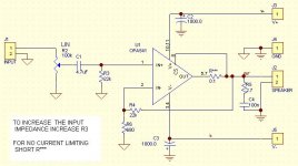
Based on the Data sheet: Try that one.
JojoD818 said:Hi guys,
I'm now about to try the OPA541, however, I am not sure how to connect this chip.Is there realy a resistor in series with the load?
Any diagram or pcb would be helpful. Thanks!
Based on the Data sheet: Try that one.
Attachments
Hehe, I forgot that when trying to put the supply the most far from in/out as possible ") But you say if I connect the GNDs it will work this way? The other is, that r1/r2 is clear now thanks to this thread, but what about the 2 caps? In my previous schematic they were 1000uF, but in the one at the threads beginning they are 10uF. Are these only for filtering the power, and their value depends on the used power supply?
But you say if I connect the GNDs it will work this way? The other is, that r1/r2 is clear now thanks to this thread, but what about the 2 caps? In my previous schematic they were 1000uF, but in the one at the threads beginning they are 10uF. Are these only for filtering the power, and their value depends on the used power supply?
dArk
But you say if I connect the GNDs it will work this way? The other is, that r1/r2 is clear now thanks to this thread, but what about the 2 caps? In my previous schematic they were 1000uF, but in the one at the threads beginning they are 10uF. Are these only for filtering the power, and their value depends on the used power supply?dArk
- Status
- This old topic is closed. If you want to reopen this topic, contact a moderator using the "Report Post" button.
- Home
- Amplifiers
- Chip Amps
- How to use OPA549 and OPA541?