Hi guys,
I recently made a webpage about DIY that includes the OPA549 and OPA541 chipamps with pcbs.
http://www.geocities.com/jojod818/index.html
JojoD
I recently made a webpage about DIY that includes the OPA549 and OPA541 chipamps with pcbs.
http://www.geocities.com/jojod818/index.html
JojoD
JojoD818 said:Hi guys,
I recently made a webpage about DIY that includes the OPA549 and OPA541 chipamps with pcbs.
http://www.geocities.com/jojod818/index.html
JojoD
nice website, but i have noticed to mistakes on the links to the OPA541 and the Test Power Supply Unit pages. have you seen my website? http://www.freewebs.com/matttcatttweb/audio.htm
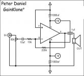
I also have a question, seeing that this is an OPA541/9 thread, what is the best way to zero the ofset of an OPA541/9 amp? i have used the following circuit:
help apreciated, thanks in advance,
Matthew
Attachments
Matt,
What errors did you find? I checked the website and it is working fine?
I visited your site but I can't view the pics.
As for the offset, my 541 has a 0.02V while my 549 0.01V using standard components, nothing special.
A way to "actively zero" the offset is to use a DC servo like what is published in AN1192,
Cheers,
JojoD
JojoD818 said:Matt,
What errors did you find? I checked the website and it is working fine?
I visited your site but I can't view the pics.
As for the offset, my 541 has a 0.02V while my 549 0.01V using standard components, nothing special.
A way to "actively zero" the offset is to use a DC servo like what is published in AN1192,
Cheers,
JojoD
if you look at the web address of the links to the OPA541 and the Test Power Supply Unit pages. they link to pages on your hard drive, not hosted on the web.
do you know where i can find the AN1192?
Matttcattt said:
I also have a question, seeing that this is an OPA541/9 thread, what is the best way to zero the ofset of an OPA541/9 amp? i have used the following circuit:
help apreciated, thanks in advance,
Matthew
The simplest would be a res in ser. of In+. Though those amps have jfet inputs and the ofset shoudn't be too dependent on that resistor. Make sure you don't have DC leftovers on the output of your source/preamp if you don't use input cap.
GregGC said:
The simplest would be a res in ser. of In+. Though those amps have jfet inputs and the ofset shoudn't be too dependent on that resistor. Make sure you don't have DC leftovers on the output of your source/preamp if you don't use input cap.
like this? if so, what value should i use?
Attachments
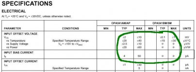
Looking at the data sheet: Ibisa-max=50pA. 50pA*220k=11uV. It means the major offset is due not to the inbalnce based on the Ib+ and Ib- rather the Vofset (Vos). Using just a resistor IMHO will not give you enough compensation -(you have to use rally high values which is not practical).
(More on that here. The input trans. are different but the concept stays the same http://www.diyaudio.com/forums/showthread.php?postid=259680#post259680). To finish that try the resistor (the one you are showing in your sch.) as Thor. sugests of 220k but I don't think it's going to work(I coud be wrong). Adding the resistor may need the cap in paralel because 220k is quite high.
You really have to add Vcomp. (from a voltage devider) at the +In. but I don’t think that’s justified having in mind you are getting only 10 and 20 mV offset (agree that still higher that the data sheet sugest). In fact looking at the data sheet (if you can believe them 100%) makes me think that there might be a measurement error coming from some noise in the output that shows at the output. Measure the offset with the pot in min (slider to GND) and max positions (no input signal though). I assume your DMM is good and it shows 0V when the leads are shorted.
Appreciate the feedback you are giving here, as I’m learning what to expect from those power amps also at the same time. In fact I’ll be ordering some samples of the OPA541 too.
By te way is it + or - 20 mV you measure?
Greg
Attachments
Mattcatt,
You can find AN1192 at national.com or just search google for it. It includes the BPA200, a bridge parallel combo that is rated at 200w. It has the servo circuit I am talking about.
Thank you for informing me about the my site, it is fixed now.
GregGC,
I agree with your observation that a resistor will not solve the offset. A better solution is to use the DC servo circuit from AN1192 that uses an integrator to minimize if not eliminate dc offset.
BTW, I use a fairly good DMM that gives 0 when leadds are shorted. My second prototype of a thw 541 and 549 shows a 0.005V when cold and a 0.007V when warm.
Both chips are well controlled and handle very well, they also sound good despite their simplicity. As of now, the bridged 549s are still powering my 12" sub quite hapilly. The sub has dual 4 ohm coils which I wire in series for an 8 ohms impedance.
This weekend, I will venture in the bridge/parallel combination using a balance driver so that all 4 amp cells are in the non-inverting mode instead of the 2 cells in inverting and 2 cells in non-inverting. I believe that with this type of setup, a larger headroom can be realized.
Cheers,
JojoD
JojoD,
That's what I'd expect from those amps as an output DC. Good to hear that.
Matt,
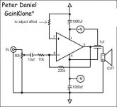
Following is just an example of DC compensation (that I wouldn't use at all). I personally wouldn't do anything to correct the output DC (accept the additional resistor from +in to GND). It seams OK. Adding additional components/circuitry increases the possibility to deteriorate the sound and contradicts with the concept of the GC - "Less is More". But at the end is all up to you. Whatever makes you feel better.
Greg
That's what I'd expect from those amps as an output DC. Good to hear that.
Matt,
Following is just an example of DC compensation (that I wouldn't use at all). I personally wouldn't do anything to correct the output DC (accept the additional resistor from +in to GND). It seams OK. Adding additional components/circuitry increases the possibility to deteriorate the sound and contradicts with the concept of the GC - "Less is More". But at the end is all up to you. Whatever makes you feel better.
Greg
Attachments
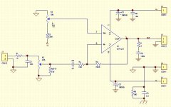
theChris said:i assume the down arrow is analog ground? and the normal ground is power ground? make sure to tie them together at the star-ground.
also, is it possilbe to have a negative DC-offset?
They are connected on the right side of the sch.
It is possible to have -DC.
Check http://www.diyaudio.com/forums/showthread.php?postid=260959#post260959 the peace of data sheet. It says Vos= +/-10mV. More than that and it should go to the garbadge. It depends on the manufacturing process.
GregGC said:JojoD,
That's what I'd expect from those amps as an output DC. Good to hear that.
Matt,
Following is just an example of DC compensation (that I wouldn't use at all). I personally wouldn't do anything to correct the output DC (accept the additional resistor from +in to GND). It seams OK. Adding additional components/circuitry increases the possibility to deteriorate the sound and contradicts with the concept of the GC - "Less is More". But at the end is all up to you. Whatever makes you feel better.
Greg
im not really that bothered, but most other people are, so i think that i should have a look at it. 10mv seems fine to me. my amps have ~40mv at the moment, i think, and running 4 chips parrelleled, i think that it could damage them if current runs between them. they get quite warm at no load, which my other amp (single chip per channel) doesnt.
are you sure it needs to be fed -v? so that should work?
i think that the sever that i host my images with is down, as i cannot view the site, and my images do not show up. i will try and re-host them soon.
Matttcattt said:
im not really that bothered, but most other people are, so i think that i should have a look at it. 10mv seems fine to me. my amps have ~40mv at the moment, i think, and running 4 chips parrelleled, i think that it could damage them if current runs between them. they get quite warm at no load, which my other amp (single chip per channel) doesnt.
are you sure it needs to be fed -v? so that should work?
i think that the sever that i host my images with is down, as i cannot view the site, and my images do not show up. i will try and re-host them soon.
Matttcattt,
Are you absolutely sure there are no oscillations present at the output of the amp?
I’m not sure it has to be –V. Depends what polarity your DC output offset is. If it’s – than you have to apply + to the +In. If it’s + then you apply – to move it to the other direction. Keep in mind that this compensating voltage is applied directly to the input of the amp and any type of ripple or noise that rides on the DC will be amplified also and you’ll get it at the output. So that –V has to be really clean. That’s why I don’t think you should do that but rather see if there are other reasons for the offset (oscillations or circuit topology or component values or layout/wiring). As far as being warm, if you use +/-30V per rail, and assume 50mA quiescent current, the power dissipated by 4 amps would be 60*0.05*4=12W. If they all share one heat sink expect it to be warm. Again the best is if you show me the specific sch. with all the voltages and component values and IC type. Exactly the way you have it connected. Do you have access to a scope? Sorry about being wishy-washy here, but there are so many possibilities. If it's this (http://www.diyaudio.com/forums/showthread.php?postid=260771#post260771) circuit and you use opa541 there shouldn't be much DC on the output IF you have a single amp.
About damaging the amps: Again, exactly how are they connected together?
Mattcatt,
Dissipation without load is what the DC servo in AN1192 minimizes, if each cell amp has reduced offset then the problem of current flowing to a cell amp would be minimized. I suggest that you download that app note. If the dc servo is too hard to make for you (like me), then there is a a basic way using dc blocking capacitors also discussed in AN1192. Also, matching components can help minimize heat dissipation in parallel/bridge combo.
In my recent unfinished prototype, I did not use the dc servo, just plain old non-inverting mode with capacitors in the input of each amp cell. Decoupling caps all around too.")
Like you, I am not too worried with the heat dissipation nor the offset, my plan is to build it simple then work my way up.
Regards,
JojoD
Dissipation without load is what the DC servo in AN1192 minimizes, if each cell amp has reduced offset then the problem of current flowing to a cell amp would be minimized. I suggest that you download that app note. If the dc servo is too hard to make for you (like me), then there is a a basic way using dc blocking capacitors also discussed in AN1192. Also, matching components can help minimize heat dissipation in parallel/bridge combo.
In my recent unfinished prototype, I did not use the dc servo, just plain old non-inverting mode with capacitors in the input of each amp cell. Decoupling caps all around too.
Like you, I am not too worried with the heat dissipation nor the offset, my plan is to build it simple then work my way up.
Regards,
JojoD
GregGC said:
Matttcattt,
Are you absolutely sure there are no oscillations present at the output of the amp?
I’m not sure it has to be –V. Depends what polarity your DC output offset is. If it’s – than you have to apply + to the +In. If it’s + then you apply – to move it to the other direction. Keep in mind that this compensating voltage is applied directly to the input of the amp and any type of ripple or noise that rides on the DC will be amplified also and you’ll get it at the output. So that –V has to be really clean. That’s why I don’t think you should do that but rather see if there are other reasons for the offset (oscillations or circuit topology or component values or layout/wiring). As far as being warm, if you use +/-30V per rail, and assume 50mA quiescent current, the power dissipated by 4 amps would be 60*0.05*4=12W. If they all share one heat sink expect it to be warm. Again the best is if you show me the specific sch. with all the voltages and component values and IC type. Exactly the way you have it connected. Do you have access to a scope? Sorry about being wishy-washy here, but there are so many possibilities. If it's this (http://www.diyaudio.com/forums/showthread.php?postid=260771#post260771) circuit and you use opa541 there shouldn't be much DC on the output IF you have a single amp.
About damaging the amps: Again, exactly how are they connected together?
JojoD818 said:Mattcatt,
Dissipation without load is what the DC servo in AN1192 minimizes, if each cell amp has reduced offset then the problem of current flowing to a cell amp would be minimized. I suggest that you download that app note. If the dc servo is too hard to make for you (like me), then there is a a basic way using dc blocking capacitors also discussed in AN1192. Also, matching components can help minimize heat dissipation in parallel/bridge combo.
In my recent unfinished prototype, I did not use the dc servo, just plain old non-inverting mode with capacitors in the input of each amp cell. Decoupling caps all around too.
Like you, I am not too worried with the heat dissipation nor the offset, my plan is to build it simple then work my way up.
Regards,
JojoD
I seem to have hijacked this thread, so sorry everyone.
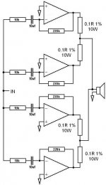
GregGC, the outputs of each amp are conected together with 0.1R 10W resistors. see image.
I do have access to an osciliscope(sp?), and i really should learn to use it, and check the outputs. i will do next week, if i have time.
as for components values, they are as on the diagram i posted (http://www.diyaudio.com/forums/showthread.php?postid=260771#post260771). the rail votlage is +/-15v, and will drop to +/-12v when i build my new power supply, as this amp is for my car.
i have all 16 chips of the one sheet of ~4mm aluminium, which is the heatsink. it is cooled by 4 computer fans on the underside of the heatsink. unfortunatly, i cannot show you a picture of my amp, and the pictures i took are not on this computer, and the only site they were hosted on is not closed. i will look for them on my other pc, and i will take some more if i cant find them. make take me a while though.
it is a 6 channel amp, 4 channels with chips parrelleled, and 2 with 4 chips parrelleled.
JojoD818, the servo circuit is a bit complicated, so i have just used 10uf DC blocking caps on each chip. when i have some more cash, i will put the amp in a proper box, with somw proper heatsinks, and i will have the inputs done properly, filters, buffers etc, and i will probably use the servo circuit.
thanks for you help.
Attachments
Hi,
sorry, I had no time to read the whole thread, but has anybody done a non inverted cirtuit with the OPA549?
Yesterday I done such a circuit for my sub. It has 22k on feedback and 680 from - to ground. From + to groud is is 22K. 1000u caps and a 0.68u decoupling.
At first it had very strong oscillations and got very hot. I checked everything and the wiring was just fine. After fiddling a bit (and one (test) driver dead) it started to work fine, just like that.
Strange...
Miguel
- Status
- This old topic is closed. If you want to reopen this topic, contact a moderator using the "Report Post" button.
- Home
- Amplifiers
- Chip Amps
- How to use OPA549 and OPA541?