") If i have a short wiring cable, i difficult to some maintenance (replacing some part with the other), so that's why i use a long cable, in other side i know, i will get some noise but not HUM.
If i have a short wiring cable, i difficult to some maintenance (replacing some part with the other), so that's why i use a long cable, in other side i know, i will get some noise but not HUM.If i do some grounding technique and eliminate all ground loops, i'm sure there is no HUM although i use a long and loopy wiring.That's my opinion,maybe i will try to rewiring my amp using the shortest wire. I know that the capasitance of the wire about 50pF/ft, so i will reduce my cable length

Before i re-wiring my cable i should try to find the hum source, maybe from fan noise?or the loudspeaker protector?

Any suggest?
I use a huge heatsink to make sure the amp cool, by adding a cooling fan, my amp is very cool
.But i think a cooling fan causing some noise.
Thx Mr.pinkmouse for ur suggest, i will try to re-wiring.
regards
---------
TomZ
Hi everyone!!I still need ur help to remove the slight HUM from my GC.
In a week, i do this.
1.I Have put the trafo far away from my signal wire -->Slight HUM still occured
2.I have connected each ground point (trafo's CT,PSU gnd,GC's PCB gnd) to the chassis (star ground)--->Slight HUM still there
3.I have disconnected other trafo(cooling fan and loudspeaker protector)--->Slight HUM still singing
4.I checked the connection between ground point using multimeter and all ground point are connect---->slight HUM still there. I'm sure there is no disconnected ground wire, because when i try to disconnected one of ground wire, the slight HUM become louder.
5.I have checked my PCB especially in ground route. I connect the SG&PG using a piece of wire.
6.I try to use a lower voltage from 35V DC to 25V DC----->Slight HUM become more weak.
NB:All above tested without any input signal(without CD player connected to GC) in minimum volume.
Can this slight HUM come from noise power supply/transformator?Because i buy the El transformator about $4(cheap).The slight HUM i hear is 50Hz (with a little "buzz"sound). I describe my slight HUM sound like a sound which produce from 50Hz sinewave mixed with 50 Hz squarewave.
I'm still confused with this problem although this slight HUM sound don't bother me in listening music. But when my ear close to the loudspeaker (20cm) the HUM sound become audible.Please help me.
Maybe we can share about how to removing this HUM sound.
regards
---------
TomZ
It may be worth trying to disconnect the chassis ground from the star ground point and jacks.
Do you have fluorescent light fixtures? They may be to blame. As well as light dimmers.
And, FWIW -- one reason people use toroids is because they will help get rid of hum! Regulation is better, and spill-out magnetic fields are significant smaller.
Try removing as much of your circuit as possible (loud speaker protection, input crap, etc) and see if the hum is still there with those parts (and transformers!) gone. Also, try rotating your EI transformers a few degrees, that will sometimes help them (the magnetic field is not circular; it's more like the electron position probability of an uncharged helium atom).
And remember, you should be testing with the inputs shorted to ground. It is not at all unlikely that you have hum coming from other equipment.
Wes
What do you mean?And remember, you should be testing with the inputs shorted to ground
I have tried using without pot--->the HUM still there.
Can i assumed that the problem come from El transformator?
I connect pot's gnd ---->hum still occured
what's wrong with my GC?

An unbalanced input consists of a signal wire and a ground wire. You need to connect the 2 together at the input of the amplifier while testing.What do you mean?And remember, you should be testing with the inputs shorted to ground
> Can i assumed that the problem come from El transformator?
No. You cannot assume anything, except that it is possible to produce an amp without audible hum!
Employ proper diagnostic procedure: Isolate, test, fix. I have already given you suggestions for the first two steps. You cannot simply skip them and go to the third, unless you have a penchant for wasting both time and money.
Wes
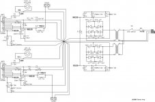
I have attached a schematic of my chip amp which shows the wiring as built. The star ground is obvious and is exactly the way the amp has been wired. There is no audible hum from this amp. It would probably be OK to use a separate star ground for each channel.
Note the input jacks DO NOT connect to the chassis where they mount on the chassis. Connecting them there is a great way to pick up hum! The input jack grounds should be tied only to the star ground (not really labeled, but pretty obvious on my schematic). This is why quality jacks come with insulating washers.
Also note, shielded cable provides an electrostatic shield, not a magnetic shield. A shield on your signal wire will protect from capacitively coupled noise, but will not help if the shielded wire is run too close to a wire carrying a lot of current or a transformer core, etc. The changing magnet field around a high current wire or transformer core will induce a current in your signal wire. The only way to prevent magnetic induction is to use something like mu metal shielding (sort of silly) or keep small signal-carrying wires away from high current wires and transformer cores. Physical layout makes a difference!
If you have a volume control in the amp, keep it close to the input jacks (you may need a shaft extension to make this work). Twist or shield input jack wires. Twist power supply wires. Keep small signal jacks and wires away from the power cord, power transformer, and power supply wiring. Keep power supply wires close to the chassis, and signal wires away from the chassis.
I_F
Attachments
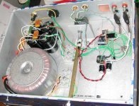
Here is a photo of the interior of the amp. I have since rebuilt using PCBs for the amp chips, but otherwise the wiring is unchanged. The star ground should be pretty obvious.
It would have been better to swap the locations of the input and output connections, and move the volume pot futher to the right, but this chassis already had right-sized holes to fit some of the jacks and I was a little too lazy to drill more.
I_F
It would have been better to swap the locations of the input and output connections, and move the volume pot futher to the right, but this chassis already had right-sized holes to fit some of the jacks and I was a little too lazy to drill more.
I_F
Attachments
 Thx Mr. I_FORGOT for ur atention. That's very nice schematic.
I have a question:
1.I have build my own pcb for my GC.In the PCB, there is 2 gnd, SG and PG.That two ground (SG&PG) i joined using a piece of wire, then i draw a cable to the chassis from that joined ground, is it right?
2.I use a chassis as a starground point but it separated in the chassis, is it ok?Because, i assumed that 1 chassis=1 starground point, is it right?
3.All wiring cable except power suply cable use shielded cable,is it ok?or i must use twisted single wire?
4.U draw many cable to starground point, is it ok if the length of the cable not same?
5.With that starground point, do you get zero HUM?
6.Is it worth if we joined the signal ground direct to the starground?
7.Which is better using PCB or P2P wiring?
I confused to make a starground point like u because i use a pcb where the SG&PG connected in the PCB not in the star ground point.
Maybe i have trouble in starground point, so i will rewiring my amp.
THx for ur attention.
regards
---------
TomZ
thomgun_lc said:
I have a question:
1.I have build my own pcb for my GC.In the PCB, there is 2 gnd, SG and PG.That two ground (SG&PG) i joined using a piece of wire, then i draw a cable to the chassis from that joined ground, is it right?
It isn't a star ground if things connect together before coming to that point! Run separate wires for signal and power grounds from your PCB to the star ground on the chassis. You will need to separate the power and signal grounds on your PCB.
Also, when connecting your power supply ground to the PCB, run one wire from the power supply to the star ground, and another wire from the star ground to the power ground on the PCB. DON'T connect a ground wire directly from the power supply to the PCB.
2.I use a chassis as a starground point but it separated in the chassis, is it ok?Because, i assumed that 1 chassis=1 starground point, is it right?
If you mean you have separate star grounds on the chassis for each amplifier channel, that should be OK, as long as each channel's power and signal grounds go to their own chassis star ground point. If you are using a single power supply to power two amplifiers, there should be separate ground wires from the power supply to each of the star grounds on the chassis.
3.All wiring cable except power suply cable use shielded cable,is it ok?or i must use twisted single wire?
Shielded cable is fine, but the shield should be connected to ground at only one end of each shielded cable.
4.U draw many cable to starground point, is it ok if the length of the cable not same?
Yes.
5.With that starground point, do you get zero HUM?
That's right, zero hum.
6.Is it worth if we joined the signal ground direct to the starground?
They should be connected, but only at the star ground point on the chassis. DON'T connect power and signal ground on your PCB then use one wire to connect them to the chassis ground. The wire has some finite (non-zero) resistance. As the power supply current flows through the ground wire there will be some voltage drop across the length of the wire. That voltage will directly modulate the signal ground voltage.
7.Which is better using PCB or P2P wiring?
It depends. I prefer PCBs for IC circuits because the connections are very close together and therefore very easy to cause a short of something gets bumped/moved. A PCB is much more stable in that regard. Either method works fine. It's a matter of personal preference. I also like to use teflon insulated wire, not because it "sounds better", but because the insulation doesn't melt when I solder the wire.
I confused to make a starground point like u because i use a pcb where the SG&PG connected in the PCB not in the star ground point.
Maybe i have trouble in starground point, so i will rewiring my amp.
THx for ur attention.
I think a lot of your hum problems will go away if you separate the signal and power grounds on your PCB.
Keep us posted on your progress...
I_F
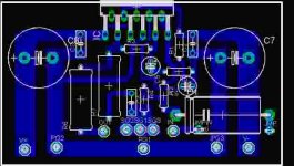
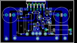
thomgun_lc said:I'm sory for the poor image, this is the good pcb image
It looks like there are separate connections for signal and power ground on your PCB. If you just run a wire from each to the star ground on the chassis you should be OK. Don't put a jumper on the PCB to connect them together! They have separate pads on the PCB for a reason- HUMMMMMMMMM!
A couple more items to note:
If you use a single power supply for multiple amplifier channels, each amplifier should have a separate wire connecting to the + terminal of the supply, and each amplifier should have a separate wire to the - terminal of the supply. DON'T make a + bus and a - bus and connect amps to them at different points- i.e don't daisy-chain the wiring from the power supply to the amps. Think of it as a star + and a star - connection, just like star ground. Each thing that connects to + should have a wire to + on the power supply, AT THE POWER SUPPLY. The schematic I posted doesn't show it explicitly- I should update the drawing...
One of your outputs for the amp comes from ground. Connect the output jack directly to the star ground point, NOT some ground point on the PCB.
I_F
Thx Mr.I_forgot for ur solution.U can see my pic of GC's amp in this post (in page2).
I use 1 El transformator 25-CT-25 then for the rectifier i use 2 rectifier, so i have separated power supply using 1 trafo.
Actually the output from the transformator only 25-CT-25, then i parralel them and go to separated rectifier
.Ground in power supply i draw directly from CT.Is it Ok?Or i must draw a ground from star ground?
Have u tried build a power supply using El transformator?I never try toroidal transformator because it's very expensive.
A good PCB (3886 BrianGT) joined the SG and PG together in the PCB, and many people which use this PCB don't complain about HUM problem, how they do that?
U can see that SG&PG joined in the PCB, which mean it isn't real starground.This is BrianGT PCB link
http://www.diyaudio.com/forums/showthread.php?s=&threadid=49813&perpage=10&highlight=&pagenumber=1
Thx a lot for the solution Mr.I_forgot, HUM is a very complex problem for me.
This is a good thread for us which have a ground problem
regards
---------
TomZ
Conflicting Directions? [star ground & wire twisting]
Hey, I_Forgot -- you suggest not running ground directly from power supply PCB to amplifier PCB, but rather running both to star ground.
Then you suggest twisting the power supply leads.
Is this conflicting direction, or did you mean to twist V+ and V- together? Normally, when I twist leads, one is ground.
Thanks,
Wes
Re: Conflicting Directions? [star ground & wire twisting]
It would be best to connect the CT to the star ground.
All the same principles apply.
I had not noticed that ground jumper before. I would recommend cutting that trace on the PCB and running separate wires to the star ground.
You are not alone. Hum and noise is a difficult problem for everyone.
That is called a bleeder resistor. It is there to ensure that the substantial capacitance in the power supply is fully discharged when I open the amp for repairs or modifications. Strictly speaking it is not necessary as the amp chips do a good job of draining the charge off the caps, however, if the amp chips blow (a reason for me to open the box and work on the thing) they may no longer drain the caps. The resistor is cheap insurance.
Some countries don't use grounded outlets. As long as you are careful to keep HV stuff away from the chassis it shouldn't be a problem. Grounded outlets are supposed to be a safer. I think the idea is that if everyone uses them and connects the power line ground to their chassis, no one will get a shock from touching two pieces of equipment where one has a "hot" chassis.
If you look carefully at the photo I posted, you can see that I twisted wires from the PS caps together and ran to a terminal block. There is one + lead twisted with a ground wire, and one - lead twisted with a ground wire going into the terminal block. From the terminal block there is one ground lead going to the star ground and there are two sets of twisted red and black leads from the + and - terminals to the two amplifier boards. I suppose it might be better to twist each red and black wire around a ground wire, but there's only so many wires you can connect to a single star ground. This seems to work well.
Unfortunately it can be difficult to mechanically arrange all the best practices... If I were to do it over, I'd swap the output and input jack locations, use a separate star ground for each channel, and twist each power supply lead with a ground wire which would then connect to the same channel's star ground. The reason I don't rebuild it now is that it is working really well. The chances of improving anything are minimal, while the chances of screwing something up during the rebuild are >0. Like they say in the Navy, "if it ain't broke, don't fix it!"
There is a very good book about grounding and shielding techniques called (surprise!) "Grounding and Shielding Techniques in Instrumentation" by Ralph Morrison. Rane used to have (still does?) some good .pdf files on their web site about grounding and shielding audio equipment, and I think Jensen Transformers did/does also.
I_F
thomgun_lc said:
Ground in power supply i draw directly from CT.Is it Ok?Or i must draw a ground from star ground?
It would be best to connect the CT to the star ground.
Have u tried build a power supply using El transformator?I never try toroidal transformator because it's very expensive.
All the same principles apply.
A good PCB (3886 BrianGT) joined the SG and PG together in the PCB, and many people which use this PCB don't complain about HUM problem, how they do that?
Thx a lot for the solution Mr.I_forgot, HUM is a very complex problem for me.
This is a good thread for us which have a ground problem
I had not noticed that ground jumper before. I would recommend cutting that trace on the PCB and running separate wires to the star ground.
You are not alone. Hum and noise is a difficult problem for everyone.
thomgun_lc said:Mr.I_forgot i have a question:
1.In ur PSU design, why you add a R1(3,3k)between two rail V+&V-??
That is called a bleeder resistor. It is there to ensure that the substantial capacitance in the power supply is fully discharged when I open the amp for repairs or modifications. Strictly speaking it is not necessary as the amp chips do a good job of draining the charge off the caps, however, if the amp chips blow (a reason for me to open the box and work on the thing) they may no longer drain the caps. The resistor is cheap insurance.
2.If i see your schematic, it looks like that u use 3phrong (Active,Neutral,Earth).In my country, i only have 2phrong(Active&Neutral+Earth).Is it a problem?
Thx a lot
Some countries don't use grounded outlets. As long as you are careful to keep HV stuff away from the chassis it shouldn't be a problem. Grounded outlets are supposed to be a safer. I think the idea is that if everyone uses them and connects the power line ground to their chassis, no one will get a shock from touching two pieces of equipment where one has a "hot" chassis.
wes-ninja250 said:Hey, I_Forgot -- you suggest not running ground directly from power supply PCB to amplifier PCB, but rather running both to star ground.
Then you suggest twisting the power supply leads.
Is this conflicting direction, or did you mean to twist V+ and V- together? Normally, when I twist leads, one is ground.
Thanks,
Wes
If you look carefully at the photo I posted, you can see that I twisted wires from the PS caps together and ran to a terminal block. There is one + lead twisted with a ground wire, and one - lead twisted with a ground wire going into the terminal block. From the terminal block there is one ground lead going to the star ground and there are two sets of twisted red and black leads from the + and - terminals to the two amplifier boards. I suppose it might be better to twist each red and black wire around a ground wire, but there's only so many wires you can connect to a single star ground. This seems to work well.
Unfortunately it can be difficult to mechanically arrange all the best practices... If I were to do it over, I'd swap the output and input jack locations, use a separate star ground for each channel, and twist each power supply lead with a ground wire which would then connect to the same channel's star ground. The reason I don't rebuild it now is that it is working really well. The chances of improving anything are minimal, while the chances of screwing something up during the rebuild are >0. Like they say in the Navy, "if it ain't broke, don't fix it!"
There is a very good book about grounding and shielding techniques called (surprise!) "Grounding and Shielding Techniques in Instrumentation" by Ralph Morrison. Rane used to have (still does?) some good .pdf files on their web site about grounding and shielding audio equipment, and I think Jensen Transformers did/does also.
I_F
Hi, again this is my report progress in removing HUM.
1. I have disconnected SG&PG and Connect to StarGround---->Loud Humming Sound+Hizz sound
Before i do that, the cooling fan sound is louder than a slight Hum, after i separate SG&PG and connect to STARGROUND, a Hum sound is louder than cooling fan sound.I think this is a fault.
Long cable = loud HUM sound.
2.I'm still confused to determine which is Slight HUM sound or Oscillation sound?Does anyone know how to recognize them without scope?
3.My conclusion is, El transformator is not good as toroidal transformator which provide minimal HUM.
Mr.I_forgot, Maybe you can add led in series with your bleeder resistor as an indicator, so you can make sure if the caps are fully discharging.
I use a 2A fuse in each rail to prevent short circuit.
Thank TOu very Much
HUM make me Sick and confused
1. I have disconnected SG&PG and Connect to StarGround---->Loud Humming Sound+Hizz sound
Before i do that, the cooling fan sound is louder than a slight Hum, after i separate SG&PG and connect to STARGROUND, a Hum sound is louder than cooling fan sound.I think this is a fault.
Long cable = loud HUM sound.
2.I'm still confused to determine which is Slight HUM sound or Oscillation sound?Does anyone know how to recognize them without scope?
3.My conclusion is, El transformator is not good as toroidal transformator which provide minimal HUM.
Mr.I_forgot, Maybe you can add led in series with your bleeder resistor as an indicator, so you can make sure if the caps are fully discharging.
I use a 2A fuse in each rail to prevent short circuit.
Thank TOu very Much
HUM make me Sick and confused- Status
- This old topic is closed. If you want to reopen this topic, contact a moderator using the "Report Post" button.
- Home
- Amplifiers
- Chip Amps
- How to removing the ******* HUM sound from our GC??