Can someone summarize the problem for me in 100 words or less?
Amps have been in service for many years with no problems. Due to current-hungry speakers, owner decided to parallel some extra OPS.
Unfortunately, the PCB didn’t have the real estate for more than a pair (1N + 1P), so methods involving high-current wire were employed.
One working mono amp was built with 4 x N (16A Lateral) + 4 x P Exicon devices.
Working amp was happy, even at high bias, i.e. 3.5A (+/-75v), and output DC never went above 15mV
Because the owner doesn’t listen in mono, another identical mono amp was built – identical in all dimensions and wire lengths.
“Identical” amp wouldn’t play ball, even with Vgs being matched to within 0.4mV on all devices. -32v was observed at the output and dummy load would get hot fast. Zobel network was cold… No fuzzy traces observed on oscilloscope… Amp seemed to work at very low voltages, but above about +/-9v the waveform collapsed and DC started amassing at output.
Lateral devices were sent back to OEM and tested on Curve Tracer – no issues reported.
VAS from working amp (everything bar OPS) was swapped onto MOSFETs from faulty amp and same problem occurred. The working bank of 8 (4N+4P) was fine with any VAS, but the other available MOSFETs (8 of each) wouldn’t work with either VAS in any combination.
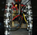
Eventually, the owner decided that he’d compromise with just 2 x N + 2 x P per amp (making wiring logistics much easier), but build 4 amps and bi-amp. This enabled him to keep the Source and Gate wires extremely short (see photos in previous posts) – so far, DC has not exceeded 5mV. In original wiring arrangement (dictated by physical constraints of extra FETs), it was impossible to get any amount of MOSFETs working… MOSFETs only work if mounted within about 2” of PCB…
The odd thing is that the first amp built was perfectly happy, but could not be emulated with other amps, even if entire VAS were swapped.
That’s more than 100 words…
Many thanks in advance for any comments you might have.
Justin
Thanks very the fine synopsis.
The important thing to note is that it's unlikely to be a
mystical problem associated with layout and such.
Far more likely to be a bad part.
Are those really 100 ohm resistors on the Gates? Is it possible
that one of them is open or a much higher value?

The important thing to note is that it's unlikely to be a
mystical problem associated with layout and such.
Far more likely to be a bad part.
Are those really 100 ohm resistors on the Gates? Is it possible
that one of them is open or a much higher value?
Nelson Pass said:
OK, the Cherubim have carried your pleas to Mount Olympus.
I will check my Bullfinch's Classic Mythology, but I am pretty certain that Zeus mostly listened to his wife.
(btw, the Ancient Greeks had demi-gods, but no angels. )
You can use a trimpot to determine the value of the gate resistors in any circumstance -- if you have a 'scope to look at the shape of the rise and fall -- with incorrect value of Rg the output waveform will "kink" -- Huebner did this with a 2 V, 1kHz square wave which probably threw the amplifier into a paroxysm of rage.
Or if you don't have a scope, you can set the ratio of P and N-Channel gate resistors to be inversely rated to the relation of Ciss, and make a leap of faith (that's where I include the mysticism) by using the Ciss values in the datasheets of the respective devices.
Nelson Pass said:Thanks very the fine synopsis.
The important thing to note is that it's unlikely to be a
mystical problem associated with layout and such.
Far more likely to be a bad part.
Are those really 100 ohm resistors on the Gates? Is it possible
that one of them is open or a much higher value?
Thanks for your comments, Mr Pass
The Gate resistors are 220 Ohm for N-Ch and 100 Ohm for P-Ch. The one thing I do know is that there is absolutely no chance of a faulty resistor. I know this because, having the impression something mystical was going on with the layout, I've rearranged it so many times that I must have gone through a reel of each resistor (I replaced the resistors after each layout attempt).
When I tried higher values of Gate R, the DC offset seemed to get worse... Lower values (100R -N / 100R -P) didn't yield any difference.
It should be noted that I couldn't even get a complementary pair working with the previous layout, yet I have a quad working now. The only difference here is a couple less inches on the Source and Gate wiring. However, I could've been unlucky when I shut down the pairs from 4-pair to 3-pair etc, i.e. the last pair had a fault...
My Atlas tester (only gives 2 parameters) says all FETs were ok.
Profusion tell me all is ok with their Tracer.
One odd thing is that one FET seems dead after coming back from Profusion…(out of 24)
Note that Profusion refunded me for 8 FETs, so their service has been good (as ever, although I did pay for 16 FETs)
Whenever I've grabbed a comp pair at random and wired them right on the PCB with minimal wiring, all has been fine...
I wonder if Rod Elliot has told anyone about the layout issues mentioned on his site with his similar Hitachi-based amp?
I've attached a photo of the original layout. It's barely any different, apart from the multi-strand 30A cable connecting to the 1.25mm copper bar for the Source, instead of the solid wire going straight to the PCB that I now have - remember that I had 1 happy amp with this arrangement, but the FETs (all 8 x N and 8 x P I had to choose the 4N+4P from) wouldn't work regardless of which ones I chose. The Gate wiring is longer here, distributed from a 1.25mm bar…I wonder if this is an issue?
Thanks again,
Justin
Attachments
Nelson Pass said:I think in terms of bad parts because I've simply never had
a case of wiring layout causing output stage issues. Not that
it can't be accomplished, but it's not like I'm always very careful,
either.
Can you see any obvious errors from the photos / text? I have Randy Sloane's book (I know the experts here won't be too impressed!) and it appears that he uses multi-strand cable to mount Lateral FETs externally, and he's quite liberal with the length of the cable in the photos...
Thanks,
Justin
aandy said:did you look at my pictures justin?
Yes, thanks!
With all your OPS on a PCB, I'm not totally sure how they apply to my issues, but your amps are certainly engineered well.
Justin
aandy said:i built thousands of amplifiers with semilab fets 1k is optimum.
andy
typically the N-channel lateral MOSFET will have Ciss about 1/3 lower than the P-channel lateral MOSFET. Thus the f(-3dB) of the P-channel will be about 50% higher.
perhaps it's optimum from the standpoint that it only notches down the measured distortion by a hair...
when a fet goes bang and they do at 1k gate R it will tend to blow the top off the dead fet without killing the drive chain.
at 100r it will most times kill the drive.
this will reasult in the amp still working for years.
and with the to3 semilab fets this normaly melts a hole in the can!
at 100r it will most times kill the drive.
this will reasult in the amp still working for years.
and with the to3 semilab fets this normaly melts a hole in the can!
> I think in terms of bad parts because I've simply never had
a case of wiring layout causing output stage issues.
Could it be that you are using IRF parts with high-ish capacitances?
My experience, with e.g. 2SK1529, shows that lower capacitance MOSFETs are sensitive to layout, especially the length of lead from the driver stage. Increasing gate resistor helps most of the time, but not always. For lateral FETs (Hitachi or Semelab), I would not hesistate to try 1k or higher.
Patrick
I wonder what the end result was. If you still are involved with the problem let me know, I have a few ideas. And I must agree that several factors increase the risk of instability (the CCS modification, lead length, parallel MOSFETs, plus some of the suggestions of adding caps). You need a good way to spot RF oscillation quickly and reliably when testing amplifiers. Of course, it might be a different problem entirely. That -32v is suspicious (but it might be a quirk of your meter responding to RF?).
I have a similar problem with my EC prototype which tends to oscillate as well. Things you might find solve the problem are:
1. Add ferrite beads in the gate pin close to each FET.
2. Use shielded gate wire, grounded in one end.
3. Use gate zobel filters as suggested by Bob Cordell - very smart trick!
4. Add source resistors, say 0,22 ohms.
1. Add ferrite beads in the gate pin close to each FET.
2. Use shielded gate wire, grounded in one end.
3. Use gate zobel filters as suggested by Bob Cordell - very smart trick!
4. Add source resistors, say 0,22 ohms.
Suzy Jackson is working with electronics as a professional.
We can see how Suzy J did it.
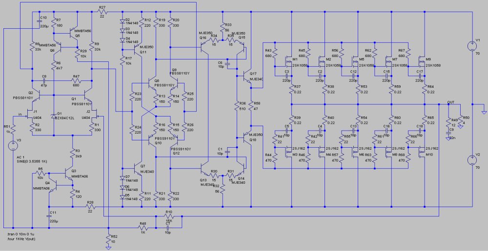
She parallels 2SK1058 and 2SJ162
Like Rickard said, she uses 0.22 Ohm source resistors.
I think this is a very good idea!
She uses 680 (for N) and 470 (for P) Ohm Gate resistors.
She also does some compensation with caps, different for N and P-channel.
Topic:
http://www.diyaudio.com/forums/solid-state/106186-capabilities-2sk1058-2sj162.html
Schematic with paralleled SK1058/SJ162:
http://www.diyaudio.com/forums/atta...-capabilities-2sk1058-2sj162-humungus_amp.jpg
We can see how Suzy J did it.
She parallels 2SK1058 and 2SJ162
Like Rickard said, she uses 0.22 Ohm source resistors.
I think this is a very good idea!
She uses 680 (for N) and 470 (for P) Ohm Gate resistors.
She also does some compensation with caps, different for N and P-channel.
Topic:
http://www.diyaudio.com/forums/solid-state/106186-capabilities-2sk1058-2sj162.html
Schematic with paralleled SK1058/SJ162:
http://www.diyaudio.com/forums/atta...-capabilities-2sk1058-2sj162-humungus_amp.jpg
Note that putting resistors in series with the source spoils the "square law" characteristic of the output stage, however the overall THD may still be good enough (assuming the bias is set okay)... not so sure about high-order harmonics (or power efficiency!) though. There comes a point with paralleling lots of expensive output transistors where a significantly different circuit in the first place might have been a better starting point.
Hi,
Shortly after posting the thread here, I got the amps working without any radical modifications. It transpires there was some kind of fault in one of the MOSFETs. It's 3 years on, so I can't quite remember what exactly, but Profusion were extremely professional and replaced the part. I've been enjoying the amps daily ever since (without source resistors) and get compliments from all who hear them. They like to be biased hot though - not the world's most efficient way to run amps. Offset fluctuates a touch, but doesn't exceed 5mV if memory is correct.
Shortly after posting the thread here, I got the amps working without any radical modifications. It transpires there was some kind of fault in one of the MOSFETs. It's 3 years on, so I can't quite remember what exactly, but Profusion were extremely professional and replaced the part. I've been enjoying the amps daily ever since (without source resistors) and get compliments from all who hear them. They like to be biased hot though - not the world's most efficient way to run amps. Offset fluctuates a touch, but doesn't exceed 5mV if memory is correct.
- Status
- This old topic is closed. If you want to reopen this topic, contact a moderator using the "Report Post" button.
- Home
- Amplifiers
- Solid State
- How to Parallel Lateral MOSFETs...