hi Justin,
>> also if they are commoned in this way how will you insulate the L bracket/heatsink from ground?
>I was going to buy a strip of silicon rubber compound (the same as the semiconductor mounting strip) and cut it to size – you can get it from Farnell
then there is the difficulty of insulating the fixing bolts as well.
i think the heat sink and bracket would be better off solidly grounded.
with regard to the offset problem things to check are solder shorts/whiskers, Iq adjust pot these give trouble, the transistors ,( check for shorts, low gain and leaky), diodes, resistors. pull them and test them. check earthing arangements, input earth connected? etc.
the sugestion of breaking down the problem is a good one. i would test the amp without the extra fets first of all,
check the DC conditions and compare with the other working unit wilst doing this i would substitute the DC fuses with 10R 2watt resistors, just in case of problems they will burn up and save the mosfet's. keep the Iq low 100mA.
check the VAS current, (1V DC across R11), corresponding to 10mA in VAS.
making sure that the amp is perfectly stable, check on a scope for any sign of instability with a range of Iq 0 to say 150mA, wilst monitoring the Iq with a meter. the Iq should increase evenly as you turn the adjuster, not jump around violently. tested with no load.
when you are satified that there is no problems with instability remove the 10R resistors, set Iq, test with dummy load all the way up to clipping. observing the scope, when you are satisfied that all is well the add the other fets. good luck
regards
bob
Hi Bob,
>then there is the difficulty of insulating the fixing bolts as well.
>i think the heat sink and bracket would be better off solidly grounded.
Insulating the bolts is easy. I can make up some bushes from Delrin / Acetal, like the semi mounting bushes, but larger.
Your advice to ground the bracket is in keeping with traditional, tried-and-tested amp-building theory. Who do I trust: the traditionalists, or Profusion’s apps data?
>i would test the amp without the extra fets first of all,
If I remove the PCB from the case, just connecting a single N+P pair – notably with very short wiring to the PCB, everything is absolutely fine, with any pair of MOSFETs: Iq goes up progressively, in a linear manner as I adjust the pot, all looks fine on the ‘scope, DC offset below 10mV. The problem comes when I want to parallel up the MOSFETs…
As I have a second pair of PCBs, I’m wondering if it would be simpler to split the FETs up, with (2 x N) + (2 x P) on FOUR amps, instead of (4 x N) + (4 x P) on a stereo pair. That way I can bi-amp, and the wiring for the FETs will be a lot shorter…
Should I throw in the towel and go for 4 boards in a bi-amp configuration? Going for 4 amps will involve a lot of metalwork…
Thanks again to all – I’m very grateful.
Justin
the symptoms sound like oscillation problems to me also.
as already mentioned, adequate bypassing close to the mosfets is very important. sound is grounding and lead dress in general.
i built this design years ago from the Hitachi manual. worked ok for me. a couple of things:
are the second stage semiconductors all good (within spec)?
are the 27pF really 27pF, not 2.7pF and are the solder joints good?
i threw a cap across the trimpot (before i got rid of it and used something else - if that pot opens, strange and wondrous things may happen )
)
good luck!
mlloyd1
as already mentioned, adequate bypassing close to the mosfets is very important. sound is grounding and lead dress in general.
i built this design years ago from the Hitachi manual. worked ok for me. a couple of things:
are the second stage semiconductors all good (within spec)?
are the 27pF really 27pF, not 2.7pF and are the solder joints good?
i threw a cap across the trimpot (before i got rid of it and used something else - if that pot opens, strange and wondrous things may happen
)good luck!
mlloyd1
the magntec fets are not quite the same as the old Hitatchi fets.
they can be more trublesome than the old Hitatchi fets.
layout layout is the most important thing.
as part of my job i have seen a lot of magnatec/profusion based amps,
most problems are layout related.
decupling can be a problem with some peoples work.

andy
they can be more trublesome than the old Hitatchi fets.
layout layout is the most important thing.
as part of my job i have seen a lot of magnatec/profusion based amps,
most problems are layout related.
decupling can be a problem with some peoples work.
andy
hi justin,
i can see your frustrations with this project as i said in my post No 20 i have made loads of these things with and without extra mosfets, the wiring does make a large difference as in that post.
it always seemed to me that on some ocasions mayby a combination of tolerances with transistors etc that i had a particularly sensitive board. all the advise on wiring etc made a difference in these cases.
the 27 pf caps i would replace anyway, (difficult to test) also try slightly larger values here 33pf or even 47pf see if that helps. some of these tiny ceramics are easily damaged with heat.
i have sympathy with you regarding the conflicting advise about grounding the heatsinks, my pennys worth is just that like you i have chased my tail with these things.
see post No20
good luck
regards
bob
Ilimzn,originally posted by ilimzn
All MOSFETs have an inflection in the gm vs temperature graph
There's one more unfortunate parameter exist i.e. Variation of Id due to variation in Vds which is worst in case of Verticals.......
")
Bob - the Gate resistors have always been soldered right to the MOSFET terminal.
In one incarnation of the amp, with just a pair of devices, the Gate resistors were on a PCB, with flying leads going to the MOSFETS - it was stable...probably because of the pair, not paralleled OPS?
Thanks to all.
If anyone can give me some 'rules' regarding layout, I'd be really grateful. I could get someone to lay out a new PCB, inc. all the new OPS, but that will cost money and I could still get the same problem...I doubt any emulation would identify this issue.
Justin
We would all like to share your knowledge
Hi.
The idea of a forum is to share ideas.
If you have an idea how to solve this problem, then please share it.
There may be others now or later with similar problems.
thanks
Andy
aandy said:when you want to sort it out call me
andy
Hi.
The idea of a forum is to share ideas.
If you have an idea how to solve this problem, then please share it.
There may be others now or later with similar problems.
thanks
Andy
Lsharptec1 said:Where is Nelson Pass when we need him?
I would love to hear his comments on this topic.
Larry
You're not the only one...
From reading a few comments online, as well as asking Bruno Putzeys, it does appear to me that some designers in the modern field regard proponents of Lateral MOSFETs as cavemen...
The amp sounded good before I decided to 'upgrade' it. I could make a pair of identical amps and go for a bi-amp, or I could put the amp back to how it was and put the extra heatsinks and FETs on Ebay... The thing is, I know I'll lose a frightening amount of cash selling them on Ebay - particularly on the heatsinks which I had anodised as a one-off...

Thanks again,
Justin
Hi,
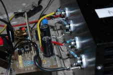
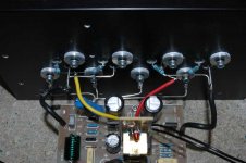
Having compromised down to just two 16A devices per side, i.e. 2 x 16A (N) + 2 x 16A (P) (the devices are paralleled 8A FETs anyway), and shortened the length of the connections, it appears to be working ok.
Whereas the original plan was to build a pair of mono amps, with each having 4 x 16A (N) + 4 x 16A (P), I now think that it will probably be for the best if I make 4 amps and biamp the speakers. I suspect this will sound better than just a pair of mono-blocks, not to mention the fact that the wiring for (4 x N) + (4 x P) will be a logistical nightmare.
Please take a look at the attachments for shots of the amp on bench. Note that this is a rough jig, things will be rewired and made neater before going into service (not to mention the addition of heatsinks to the VAS transistors).
Unless someone knows better, I’m going for 4 amps with 4 x 16A devices per amp.
BTW – Yellow lead = N-Gate, Red = P-Gate – Black 30A cable = Drain +/- and the 1.25mm wire is for the Source. I’ve also wired 2 x 1.25mm copper wire bars running on top of all the T-03 MOSFETs on the other side (print side), held in place by the screws, just to make sure there is minimal resistance between Source connections.
Thanks again to all.
Justin
Attachments
Lsharptec1 said:Where is Nelson Pass when we need him?
OK, the Cherubim have carried your pleas to Mount Olympus.
Lateral Mosfets are very easy to work with, slightly easier than
Verticals, and ordinarily people might complain that they don't
have very low distortion numbers due to their low transconductance,
but stability is not generally a problem.
Can someone summarize the problem for me in 100 words or less?
- Status
- This old topic is closed. If you want to reopen this topic, contact a moderator using the "Report Post" button.
- Home
- Amplifiers
- Solid State
- How to Parallel Lateral MOSFETs...