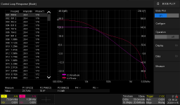
As an aside, some Siglent scopes (I have a SDS2102X Plus) are able to calculate and display Bode plots, complete with tabulated gain and phase margins, all by themselves! They use the internal (or compatible external) arbitrary waveform generator (AWG) for the frequency sweep and two input channels for the measurement. It is necessary to break the amplifier's feedback loop and run open loop to do the plot. I understand that this can be an issue for many with very high gain and/or low dc stability amplifiers. As mentioned above, DC servo loops or some small amount of broadband feedback can help. My own designs have been low open loop gain (<55 dB) with high dc stability and work very well with this cool feature. Something to consider if you are in the market for a new scope. Other brands may do this as well.

Input RC filters are generally recognized to prevent unwanted high frequency components from entering the amplifier, but that's not all. It also affects the loop gain of the amplifier.
This is mainly caused by the differential mode input capacitance of the differential amplifier circuit used in the input stage.
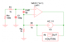
Below is a simulation in which a Laplace element with 1e6/(0.1*s+1e-6) added to the transfer function is regarded as an amplifier. This is an amplifier with DC gain 120dB dominant pole 1.6Hz, GB product 1.6MHz and ideal first-order lag characteristics.
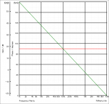
This is the result of measuring the loop gain for a circuit with a feedback factor of β=0.5 with Rf, Rb=1kΩ.


The unity loop gain frequency is 800kHz(green curve) and the phase margin (red curve) is constant at 90°. In this circuit, there is no change even if Rin=100k is shorted.
However, adding 5pF to the differential mode input capacitance results in:


The dashed line is the result of shorting Rin=100k.
When the non-inverting input is placed at such a high impedance, both loop gain and phase margin change significantly.
This is because the feedback signal also goes around to the non-inverting input side via Cdff, and this signal is input as positive feedback.
Since there are multiple poles in the actual circuit besides this, if the input is left open without being connected to anything, the circuit will become unstable and in the worst case it may lead to oscillation.
However, setting Rin to a low value means lowering the input impedance, which is not necessarily desirable. Since the stability after feedback depends on the frequency at which the unity loop gain becomes 1 (generally sufficiently higher than the audible band), the non-inverting input should have a low impedance at that frequency.
So let's add an input filter R1=1kΩ, C1=100pF.


As you can see, there is no significant change when the input is open or shorted (broken line).
BJTs and FETs used in the input stage differential amplifier circuit always have a capacitance between the base (gate) and the emitter (source). If there is a capacitance of 10pF between the base and the emitter, it is equivalent to a capacitance of 5pF between the differential base and the base in the small signal region that can be regarded as linear.

From my experience with actual circuits, it seems that this capacitance is also large in low-noise circuits (e. g. MC Phono Amp, etc.) that require alarge gm devices in the input stage, so special attention is required.
This is mainly caused by the differential mode input capacitance of the differential amplifier circuit used in the input stage.
Below is a simulation in which a Laplace element with 1e6/(0.1*s+1e-6) added to the transfer function is regarded as an amplifier. This is an amplifier with DC gain 120dB dominant pole 1.6Hz, GB product 1.6MHz and ideal first-order lag characteristics.
This is the result of measuring the loop gain for a circuit with a feedback factor of β=0.5 with Rf, Rb=1kΩ.
The unity loop gain frequency is 800kHz(green curve) and the phase margin (red curve) is constant at 90°. In this circuit, there is no change even if Rin=100k is shorted.
However, adding 5pF to the differential mode input capacitance results in:
The dashed line is the result of shorting Rin=100k.
When the non-inverting input is placed at such a high impedance, both loop gain and phase margin change significantly.
This is because the feedback signal also goes around to the non-inverting input side via Cdff, and this signal is input as positive feedback.
Since there are multiple poles in the actual circuit besides this, if the input is left open without being connected to anything, the circuit will become unstable and in the worst case it may lead to oscillation.
However, setting Rin to a low value means lowering the input impedance, which is not necessarily desirable. Since the stability after feedback depends on the frequency at which the unity loop gain becomes 1 (generally sufficiently higher than the audible band), the non-inverting input should have a low impedance at that frequency.
So let's add an input filter R1=1kΩ, C1=100pF.
As you can see, there is no significant change when the input is open or shorted (broken line).
BJTs and FETs used in the input stage differential amplifier circuit always have a capacitance between the base (gate) and the emitter (source). If there is a capacitance of 10pF between the base and the emitter, it is equivalent to a capacitance of 5pF between the differential base and the base in the small signal region that can be regarded as linear.
From my experience with actual circuits, it seems that this capacitance is also large in low-noise circuits (e. g. MC Phono Amp, etc.) that require alarge gm devices in the input stage, so special attention is required.
Attachments
Imagine a simple BJT long-tailed pair. Say its current source is 1mA and betas 100. If my memory serves, the small-signal gm of each transistor at room temperature is about 40 x 0.5mA = 0.02, and each Rpi is 5000 ohms. So the differential resistance between LTP bases is 10k ohms.
This is the same order of magnitude as the input resistor to ground in a typical amplifier.
In this scenario, the input filter components would affect the feedback loop gain, even before considering differential capacitance.
This is the same order of magnitude as the input resistor to ground in a typical amplifier.
In this scenario, the input filter components would affect the feedback loop gain, even before considering differential capacitance.
OJG,Hi!
How do you guys measure the phase margin of an amplifier?
Since you liked my post #121, I am attaching a sample Siglent Bode plot. The tabular data on the left side can be turned off, leaving a larger gain and phase plot. The measurements below the table and plot show the upper cut-off frequency, phase margin, and gain margin.
Bruce