Split bobbin transformers (the output device step-up) don't pass RF, plus the 120V output is center tapped and grounded. The output is clean before it even leaves the enclosure. If we can drive a speaker with reasonable audio quality, we can provide a clean 60 Hz quite easily. The class-D amp I use has post filtering; if there is noise I have not been able to find it on the output (doesn't matter if it's present at the amp LV terminals). The only problem is some THD as a result of the transformer's nonlinearity; the class-D chokes a little bit on it, but then again a 60Hz transformer won't pass 60Hz without some distortion of its own due to the B-H curve.
It should be stressed that DHT heating is the application for this supply. This AC supply doesn't feed another power supply with a rectifier front end; it goes directly to a load which is also the cathode of the amplifying device. If you can live with your distorted sine wave, that's great; I prefer improving performance of my amps. The hum residual at the output of the amp has been decreased significantly, though testing is ongoing.
Distortion on the AC line input is 2.5% only based on 2nd and 3rd. Output is 1%. Most significant is the higher order distortion and hash is attenuated by almost 50 dB ! That's no slouch.
Attachments
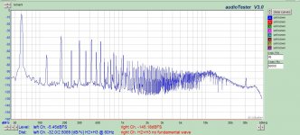
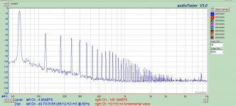
If you put 3 of them in cascade you'd get 0.0001% distortion and 150 dB of hash attenuation.Distortion on the AC line input is 2.5% only based on 2nd and 3rd. Output is 1%. Most significant is the higher order distortion and hash is attenuated by almost 50 dB ! That's no slouch.
If it were a passive filter, possibly; but this is an active amplifier (kind of behaving as an inverter) that is derived from a DC supply, so cascading probably wouldn't give me anything additional. The residual distortion is generated by the class-D amp and output transformer. This distortion is unrelated to the input distortion of the AC line. Does that make sense?
So it's going to sound like a poor version of the average (contemporary) isolation transformer?
I don't know what drives the idea that people in the industry would "skip" putting a class D device in front of their transformer, given that many of them don't spare any expense.
The only reason I'm seeing to do this, is to increase frequency. But I'm not sure it's worth the pay off at all. I'd be interested in a higher frequency, or even two or three phase, from the power plant. Most of the rewards of just increasing the frequency can be achieved with a good regulator.
I really don't understand your comments. Granted, I have not shown every last piece of the puzzle, which I thought was fairly self-explanatory. I described it rather than show every detail on the schematic.
Do you understand that the design I have submitted will take a 2% distorted AC main and reproduce a 1% AC regulated output with very low hash and higher order harmonics?
This same design will take a 20% distorted AC main and reproduce the same 1% AC regulated output?
Feed it 95VAC, feed it 130VAC, the output is 115V regulated (or whatever set point I choose).
If you don't agree then you don't understand the design. This behaves nothing like a poor version of an isolation transformer. It's closer to a low power ferroresonant transformer.
I really don't understand your comments. Granted, I have not shown every last piece of the puzzle, which I thought was fairly self-explanatory. I described it rather than show every detail on the schematic.
Do you understand that the design I have submitted will take a 2% distorted AC main and reproduce a 1% AC regulated output with very low hash and higher order harmonics?
This same design will take a 20% distorted AC main and reproduce the same 1% AC regulated output?
Feed it 95VAC, feed it 130VAC, the output is 115V regulated (or whatever set point I choose).
If you don't agree then you don't understand the design. This behaves nothing like a poor version of an isolation transformer. It's closer to a low power ferroresonant transformer.
I used that CD4046 chip before on my beginner PLL 1st of many different PLLs> if I remember correctly, not the VCO part just the phase / freq detector. I don't see a phase offset adjustment on yer diagram? I would of used a common CMOS Schmidt trigger instead of a linear +/- circuit.
do you use a NFB loop to control the class D amp output voltage level?
isn't the heater filaments "the problem" that needs to be isolated from everybody else? if then, why do you need to use a synchronized version of clean 60Hz power?
If you build it Zig, destroyer wants to audition it.
Maybe if we are all nice and ask Richard Marsh
he will run it through his test proceedure and
then we can go from there.
Make improvements tweak the thing, or
it is just perfect first time through.
************************************************
I've read through this a few times and I'm
still not sure which way we would agree on the
Felix:
1 uf, .1uf, .01 uf CMC .01 uf, .1uf, 1 uf.
The CMCs are 3.3H 4.2 amp & 4.7H 4 amp to
be used in different Felix's They only had one
3.3H.
I was going to make a few of these to try out.
Is there a consensus on what to use for the earth ground
in the felix?
I was just going to stuff them in standard wall mount
boxes. I found some "deep" plastic boxes or are the
steel conduit boxes the way to go? These are at the
big box home stores.
I've seen reference to making them short (stacking components)
but most professional layouts I've seen have space between components
like destroyers felix pics.
These are probably the best CMC's. It's a combination of filtration vs ampere vs resistance that works well in AC. Be careful to chose right ampere, exceeding the rating is very bad, and a fuse is wise.
Coilcraft Combination Line Filter Choke
The capacitor configuration is fine. I don't think the order could actually matter.
The most important factor of the box is making sure hot and neutral can't make contact with each other, ground, or the box if it conducts.
Ground can just carry through, but the box will be grounded if you put a typical receptical in the box. However you can use two Felix's per recepticle if you seperate the sockets by breaking off the tabs that connect the two.
Please be careful, and feel welcome to post pics if you want confirmation on what appears safe.
Keeping the capacitors close would reduce their lead inductance, but I wouldn't stress it. Technically if you can cross the wires in between capaictors, it'd be best. However, obviously, they need to be insulated to not conduct. If you can make PCB's, you just need to put them on different layers so they can cross in between capacitors. This is an entirely anal thing to do, but hell why not?
I give up. Were did you get the FFT plots from?Already built. Where do you think I got the FFT plots from?

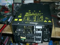
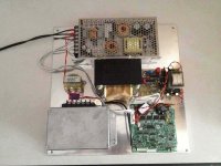
Would you mind explaining what each module is. They all look like they are commercially available "things" except the one on the right.Already built. Where do you think I got the FFT plots from?
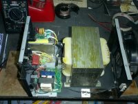
The intent was to prototype something in order to validate it would serve my design goal, so yes, there are commercial products in use. It was quicker and cheaper to buy a 48VDC switching power supply rather than to build my own (that's the one at the top) - same goes for the class-d amp (lower right).
The little xfmr on the left is no longer used (prototype version).
The pcb on the middle right is a theft from a different project; I just used it to provide the +/- 15V supplies required by the class-d amp below it.
The aluminum enclosure houses the PLL/oscillator shown in the schematics from prior posts. It takes a 120VAC input and outputs a 1V sine wave synchronized to this AC input. I discovered I had to enclose this board in an enclosure as the class-d amp was emitting EMI that was hiccupping the 4046 PLL lock. I never was a big fan of that chip, so sensitive and always in need of select-at-test.
So the 48V supply provides power to the class-d amp. The PLL/oscillator provides a clean sine wave to the amp. Amp is designed for 4 ohm loads, so the output feeds a 240/120:48V step up transformer. Primaries wired in series, so we run less than 50% saturation. VA of transformer approximately halved with this config, but I only needed about 50-60W. Amp is well within its limits, and runs quite cool, 30C rise over ambient IIRC. I can sit with my variac and bounce the input voltage from 95-135V all day long and the output is rock steady.
I really don't know how this would operate on a traditional preamp or DAC with a capacitor input rectifier - as I have stated, this is very application specific heating DHT's which are essentially resistive load. My personal opinion is there is little value to providing clean 120VAC when all you intend to do is rectify/regulate back to dc. A shielded isolation transformer is normally sufficient for that. But in keeping with the OP, this is one method to clean up your AC. All roads lead to Rome.
The intent was to prototype something in order to validate it would serve my design goal.
NICE!

Congrats,I can sit with my variac and bounce the input voltage from 95-135V all day long and the output is rock steady.
.
isn't the line range provided by the SMPS regulation?
Destroyer, Zig, Others,
I'm doing this...
Question is it this what you meant by crossing the wires over?
quick and dirty schematic...
I'm doing this...
Question is it this what you meant by crossing the wires over?
quick and dirty schematic...
An externally hosted image should be here but it was not working when we last tested it.

Destroyer, Zig, Others,
I'm doing this...
Question is it this what you meant by crossing the wires over?
quick and dirty schematic...
An externally hosted image should be here but it was not working when we last tested it.
Yes that is what I meant.
- Status
- This old topic is closed. If you want to reopen this topic, contact a moderator using the "Report Post" button.
- Home
- Amplifiers
- Power Supplies
- How to make a power conditioner