No. In fact I can't see any connection whatsoever between single supply rail and quasi comp. Has someone suggested that there is a connection?indianajo said:What really puzzles me is, is a single supply amp without center tap, inevitably quasi comp?
My understanding is that quasi comp uses a Darlington pair and a complementary pair, with the output devices being the same polarity.
You can use an output cap from any single rail amp. It doesn't have to be a quasi comp.I'm still building quasi-comp because the electrolytic speaker capacitor is a simple, elegant, and 30 year life solution to speaker preservation.
Here is an interesting point though - same outputs in quasi complementary will cancel even order harmonic distortions more so than odd orders. So it may not sound as sweet or euphonic. As we saw in the quasi thread where asymmetry is introduced by using a FET and BJT combo. Alternatively we can use same sex FETs or BJTs from different manufacturers or series it introduce asymmetry back into the outputs to enhance the harmonic profile of the distortion back to euphonic type.
So maybe IRFP240 and IRFP250's or Vishay on one side and AlFET on the other side? Or Motorola BJT on one side and Toshiba on other side.
You get the idea.
Hi,
Simply not true. Where does this misinformation come from ?
Full complementary reduces even harmonics, quasi has more.
Bad asymmetry in the x/o region is just bad, not euphonic,
even though by definition it adds even harmonics. The quasi
without a "baxandall diode" is just bad sounding, full stop.
An externally hosted image should be here but it was not working when we last tested it.
The diode makes the bias loop much more symmetrical.
rgds, sreten.
Where does this misinformation come from ?
If you read the recent thread on the quasi MOSFET amp here. And also from a private communication with a very highly regarded amp designer on this forum.
http://www.diyaudio.com/forums/soli...ple-quasi-complimentary-mosfet-amplifier.html
That type of output stage isn't what one would call quasi-comp. it makes no pretense of being complementary. The used to make them out of pnp germaniums back before the 2n3055. It's sort of a variation of the circlotron.
Circlotron is a completely different story.
Impossible without the floating power supplies.
Balanced by design.
Well, Its a heavily modified version of the schematic for a single Naim NAP250 amplifier board. The original has been in circulation for many years and is accepted as a classic Quasi-comp. design - replete with Baxandall diode. The original draft is somewhat easier to follow:

The "network" of components on the PNP driver's emitter came from three different amplifier Designers in the 1960-1970s.................................The quasi without a "baxandall diode" is just bad sounding, full stop.
An externally hosted image should be here but it was not working when we last tested it.
The diode makes the bias loop much more symmetrical...........
Shaw suggested the addition of the resistor to improve the quasi complementary performance.
Baxandall introduced the diode and kept Shaw's resistor. This implies that Baxandall agreed that the resistor introduced by Shaw was a good modification.
Finally Hood added the capacitor to the Shaw resistor and the Baxandall diode. (again confirming that he too thought the two previous improvements were correct).
We end up with the Shaw/Baxandall/Hood network of R/D/C loading up the lower driver's emitter.
I note that the post27 sch of the NAP circuit omits the Hood capacitor.
I would like to see our sim experts comparing simulator predictions for each of the Shaw, Baxandall and Hood improvements.
Last edited:
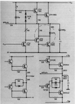
Shaw-PJB-JLLH mod
There is a minor correction to the above statement:
Shaw suggested the addition of a diode in the collector circuit. (Top pic)
PJB suggested moving the diode to the emitter of the driver and put a resister in parallel. (Bottom left)
JLLH added a capacitor in parallel to Diode and cap. (Bottom right)
JLLH
Shaw suggested the addition of the resistor to improve the quasi complementary performance. . .
We end up with the Shaw/Baxandall/Hood network of R/D/C loading up the lower driver's emitter.
... I would like to see our sim experts comparing simulator predictions for each of the Shaw, Baxandall and Hood improvements.
There is a minor correction to the above statement:
Shaw suggested the addition of a diode in the collector circuit. (Top pic)
PJB suggested moving the diode to the emitter of the driver and put a resister in parallel. (Bottom left)
JLLH added a capacitor in parallel to Diode and cap. (Bottom right)
JLLH
Attachments
Quasi means acts as if.
So quasi complimentary means the NPN's act as if they were complimentary.
I think that is a good definition.
You can draw a box around the top darlington and the bottom sziklai and then the boxes can be seen as 'devices' which act as complements to each other, although the output devices in both boxes are the same (NPN usually).
Jan
@ sreten
Did you add in the component vales in Post #22. If so why the changes, if not who did & why ?
@ Ian Finch
Thanx for the NAP upload. To me it seems the main difference between the 2 circuits, is the addition of protection components.
@ gannaji
Thanx for the upload. I seem to recall they are from a Wireless World or ETI article by JLH from the 1980's.
If you read the recent thread on the quasi MOSFET amp here. And also from a
private communication with a very highly regarded amp designer on this forum.
http://www.diyaudio.com/forums/soli...ple-quasi-complimentary-mosfet-amplifier.html
Hi,
You can't work out your totally contradicting yourself in that post ?
I'm not wading through 38 pages of posts to find the error in your thinking.
Why you can't work out its only full complementary that can reduce even
order distortion is beyond me, its the same as out of phase drivers in
push pull cancelling even order, by drive being more symmetrical.
Crude quasi complementary is far from symmetrical and does not
cancel even order in anyway, in fact even order is quite bad, as is
odd order to boot, but asymmetry guarantees lots of 2nd order.
rgds, sreten.
Last edited:
I'm not expert on topologies and how they affect even or odd order distortions. So maybe it's not correct but I am relaying what I was told by a trusted designer.
I'm paraphrasing but...
"Slight asymmetry in a quasi output will sound more pleasing due to higher 2nd and 4th vs 3rd and 5th (odd)."
I'm paraphrasing but...
"Slight asymmetry in a quasi output will sound more pleasing due to higher 2nd and 4th vs 3rd and 5th (odd)."
Do you mean one can return the speaker current to the lower rail voltage with any bipolar amp? Not the center tap?You can use an output cap from any single rail amp. It doesn't have to be a quasi comp.
I've tried back to back 5600 uf 100v caps series the speaker out on a Peavey CS800s bipolar amp. Speaker return went to the normal terminal, middle of the pnp-npn output transistors. It caused vibrato on top octave piano source. Pianos don't produce vibrato, that was a sign of HF IM distortion to me.
Possibly caused by the electrolytic caps crossing zero volts where chemical events happen.
I've looked at assembling 3300 uf 60 v film cap, Would be 8" tall in 19" rack space and cost $$$ each.
tiefbassuebertr sent me an article once about capacitor connecting any full complementary amp to speaker that I didn't understand. Something about pulling the tranformer center tap. OT Idle currents balanced by ???
The chance of me connecting these decent sounding speakers (SP2) that cost a month's pension each, to any direct connect output transistor amp, without further protection, are slim and none. The difference between .015% HD quasi comp design and .004% HD full complementary design strike me as irrelevant using speakers. 20 db down 2nd harmonic distortion (SP2)is the best sounding speaker you can find in stock in this flyover state. And the best I could probably afford anywhere. With those, the full complementary cS800s (when it was occasionally working) sounded exactly the same at 1.5 Vpp base listening level, to the quasi-comp dynakit ST120 with djoffe idle bias control circuit and NTE60 OT's (2 mhz Ft). If the djoffe idle bias circuit would stop shorting out sense transistors, I'd have stopped right there.
Last edited:
No, that is not what I said. I said single rail, so there is no centre tap.indianajo said:Do you mean one can return the speaker current to the lower rail voltage with any bipolar amp? Not the center tap?
You seemed to connect output caps with quasi comp amps. I pointed out that it is single rail amps which need a cap, not quasi comp amps. Quasi comp can be single rail or dual rail, just like fully comp amps.
Seems to me that XRK makes one mistake - we all make them on forums - he has put in a huge amount of music clips and interesting information, and the thread is running away with the smartest guys in the room.......
Yes, a quasi has asymmetrical topology and therefore produces asymmetric distortion, that is, even order. End of argument, that is the truth. Here is the FFT for the quasi at 1KHz into 8R using good models from Cordell. This is around 0.046%, and about 95.2% of this THD is H2, which is at 67dB below.
HD
Attachments
Last edited:
IMO More than one error ")
Youtube files are a ..Laughable... method to evaluate "someone else's" sound files.
Beyond that. these are often Odd digressions.. when time proven superior ones are ignored.
But then.. We all have our individual irrationalities
Not to be overly concerned though..All things will pass.. TIME.. is the great equaliser
Bare,
I have never posted any "YouTube" files - not sure what you are referring to. I record sound files in high resolution WAV format with an identical setup in the recording chain with the exception of the item under test. The item was a speaker driver in previous threads and lately, amplifiers. The common thread being the only difference in the sound clips is the exchange of the item under test. So any audible changes recorded at the mic are result of the item under test being different. No recording chain is perfect and I don't claim to have the best DAC etc. but differences in measured frequency spectra or harmonic distortion are result of changing item under test. The recorded high resolution sound clip is finally converted to 320kbit MP3 for a couple of reasons: accessibility by different people as mp3 is ubiquitous and universally available as standard fare on most OS's, and small size to fit on DIYA servers with 1.8MB file size limit. Sure, lossless FLAC is better but you would get maybe 8sec vs 45sec of duration.
I have never posted any "YouTube" files - not sure what you are referring to. I record sound files in high resolution WAV format with an identical setup in the recording chain with the exception of the item under test. The item was a speaker driver in previous threads and lately, amplifiers. The common thread being the only difference in the sound clips is the exchange of the item under test. So any audible changes recorded at the mic are result of the item under test being different. No recording chain is perfect and I don't claim to have the best DAC etc. but differences in measured frequency spectra or harmonic distortion are result of changing item under test. The recorded high resolution sound clip is finally converted to 320kbit MP3 for a couple of reasons: accessibility by different people as mp3 is ubiquitous and universally available as standard fare on most OS's, and small size to fit on DIYA servers with 1.8MB file size limit. Sure, lossless FLAC is better but you would get maybe 8sec vs 45sec of duration.
Last edited:
The person that needs a speaker cap is me - not any particular amp design. To protect from damage to my $700 speaker caused by pulling off the wires : something I've done several times over the decades with a vacuum tube amp. That speaker, SP2, brags in the spec sheet that it has <20 db 2nd harmonic distortion - so 67 db down 2nd HD of quasi comp is completely negligible .No, that is not what I said. I said single rail, so there is no centre tap.
You seemed to connect output caps with quasi comp amps. I pointed out that it is single rail amps which need a cap, not quasi comp amps. Quasi comp can be single rail or dual rail, just like fully comp amps.
The number of designs I've downloaded with speaker cap from diyaudio that are quasi comp is 23. The number of designs I've downloaded that are fully complementary output with speaker cap are zero. That is why I believe single supply amps with speaker cap have to be quasi comp. That is why I am still trying to build one. Electrolytic capacitor speaker caps sound funny crossing through zero volts.
I've expermented with RGKeen rail disconnect protection with nFETS for the fully complementary PV-1.3k but so far it is a big kluge taking 35 parts, 27 cubic inches, a separate heat sink and a separate power transformer. That is just for DC detection, not including yet speaker overcurrent protection and or heat sink overheat speaker protection. The CS800s got effective speaker protection done for $1099 retail price; the used ones available for $200 have switcher supply and blown input board etc problems.A 4700 uf series speaker cap would require two additional parts including the cinch mount strip, and take 2 cubic inches.
BTW, pulling out the 1/4 phone plug and shorting the output of the PV-1.3k caused damage destroying 127 parts by the previous owner. Including the melted PWB of the crowbar protection circuit. I don't know how many woofers he destroyed: the musician's resale shop up the road has dozens of speaker cabs with new eminence drivers due to some sort of meltdown.
Last edited:
AKSA, with a Baxandall diode and capacitor QC became a pretty oscilloscope picture, and with good global feedback applied it also sounded pretty but stinking. But should i not stick to chip amps like TDA2050 for 25W/8Ohms and LM38xx for 50W/4Ohms? Because i do not have an oscilloscope now.
Indianajoe, thou are right, that AC coupling such as output cap or transformer is the only proper way to guard a loudspeaker against amplifier failure, and double rail is usually nonsense. DC coupling audio is like picking up peas with the back of the fork.
Indianajoe, thou are right, that AC coupling such as output cap or transformer is the only proper way to guard a loudspeaker against amplifier failure, and double rail is usually nonsense. DC coupling audio is like picking up peas with the back of the fork.
- Home
- Amplifiers
- Solid State
- How to identify a quasi-complementary amplifier?