I'm not expert on topologies and how they affect even or odd order distortions.
So maybe it's not correct but I am relaying what I was told by a trusted designer.
I'm paraphrasing but...
"Slight asymmetry in a quasi output will sound more pleasing due to higher 2nd and 4th vs 3rd and 5th (odd)."
Hi,
I'm paraphrasing but...
The light asymmetry in a well designed quasi output can sound more pleasing
due to higher 2nd and 4th vs 3rd and 5th compared to a complementary
output that has lower 2nd and 4th but comparable levels of 3rd and 5th.
(Even though by definition the quasi has more THD than the complementary.)
If your designer is to be trusted, that is what he was saying.
rgds, sreten.
Last edited:
Sreten,
You are correct, but why did you have to pick a fight with XRK?
HD
Hi,
I didn't pick a fight. I said his statement was wrong.
Rather than taking my word he chose to argue about it.
In terms that don't really bear up to proper scrutiny.
I have no problem arguing about an issue with anyone.
Its not a fight, unless perceived to be. I'm guessing
you are the "trusted designer". I've no idea what you
actually stated and what stuff is in that 38 page thread.
Some people don't mind being told they have got it wrong, some
people do, but XRK strikes me as always wanting to be correct.
Your right, in that I could of just ignored it, but i picked an argument,
which I thought XRK would be up to, but I was wrong, he doesn't
understand output topology enough to see what I was saying.
rgds, sreten.
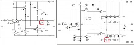
The OP simply asks what characterises a Quasi-comp. design. I don't expect members are going to concur on this but I do expect other issues about QC design and heated debate regarding personal views on audio systems generally, to be avoided here. There is already a cluster of recent threads where the high court of QC tweaking is being held, lets keep it separate when this is clearly a wiki type topic. FWIW, I think this is enough to define what QC means, though it needn't be single supply as shown here by Ian Poole. There are also other variations of push-pull and single-ended amplifiers that use single sex output devices but they don't necessarily operate as a quasi-complementary pair.
An externally hosted image should be here but it was not working when we last tested it.
Last edited:
Hi,
I'm paraphrasing but...
The light asymmetry in a well designed quasi output can sound more pleasing
due to higher 2nd and 4th vs 3rd and 5th compared to a complementary
output that has lower 2nd and 4th but comparable levels of 3rd and 5th.
(Even though by definition the quasi has more THD than the complementary.)
If your designer is to be trusted, that is what he was saying.
rgds, sreten.
I think what I said agrees with what you said - so not sure what the hub bub is.
Btw, I don't always need to be right when I am wrong. You have pointed out a couple of times in the past and I was good with it. Last time was how SPL scales with series parallel drivers IIRC.
I think what I said agrees with what you said - so not sure what the hub bub is.
Hi,
Your original post implies quasi cancels even harmonic, it simply doesn't.
Your original post implies quasi needs to be made asymmetric, it doesn't.
Fact is quasi will always be asymmetric and will always have higher even
harmonic than complementary, and the problem with quasi is to make it
as symmetric as possible, not add asymmetry as your original post implied.
rgds, sreten.
Rather than arguing a topology is or is not becomes a fetish of correctness.....
Huge threads are plain wrong, but why do we need to correct with bluntness, without grace? It brings up negative posts, and bad feeling.
I think my observation, Sreten, is that you transgressed netiquette. Most members are concerned about that, there are rules about it, and if you abide by them people might actually learn from you rather than ignoring your post and moving onto to more pleasant threads. Rather than saying it does, or does not, how about explaining WHY and leave all of us with a learning experience? With your language you should be very good at explaining the detail without rancour.
I am the 'trusted designer', but I never realised it might be possible to throw in the phrase negatively. Well done!! You are expert in the language, you can move on to the next unit now!
Hugh
Last edited:
Hello, one thing I simulated is, that a quasi-complementary output transistor made with an inverting transistor emitter resistor Re=Rc has bad clipping behaviour. On overdrive, a deep indentation shows up, where a flat should be.
Hi Grasso,
It actually depends on overall design of the amplifier. It's not good to make the OPS responsible for clipping - in most cases OPS saturation ends up with nasty artifacts. Much better approach - make VAS responsible for clipping, plus - shape it one way or the other, if required (result - OPS never clips). Then you will have clean symmetric clipping, no matter if your OPS is complementary or quasi-complementary.
Cheers,
Valery
https://www.hifiengine.com/files/images/goodmans-2.preview.jpg
For interest the Goodmans Module 80 had an all PNP ( quasi ) output stage. Nothing unusual about that except silicon. From memory 2N2955. My brother speculated that is was an older Bitish Radio Corporation germanium design quickly updated. Someone asked that it could be improved. This was just PSU caps and all signal path caps replaced, plus any low grade electrolytic. Mostly this was to please the guy. If you can just about read the circuit the VAS has a diode from emitter to rail. My brother replaced this with 56R which gave the same base voltage. He claimed this was the bigger positive change.
The owner took it with him when choosing speakers, mostly Radfords in Bristol I think. He was convinced it bettered everything the shops tried to sell him including Naim. I heard the before and after and have to say it was very different, less coloured and not unlike the Quad 303. My brother Simon said IM distortion was the only area where one could say it was different on measurement. As Simon said before the VAS mod it sounded relentless, afterwards sweet and open. I don't really mind if anyone thinks this unlikely. I mention it as someone might benefit. I often see diodes used with small valves at the cathode. I never really liked that idea.
Simon speculated that slewing is mostly the driving of the VAS ( TIS ). We did try upgrading the VAS to a higher gain device whilst keeping the diode ( 100 to 450 ). It was a very bad move.
The Creek CAS 4040 was NPN/PNP and single rail with output capacitor. If you have a very old one carefully check standing current on the outputs. It might be nearly zero! Distortion wasn't as bad as one would think. Mike speculated that hiss was it's salvation and a design mistake on his part. A kit of parts was supplied to give it more bias. The main difference being to sound sweeter and more open. Strangly not sounding bad in other ways!
Last edited:
Emitter is correct if you are putting multiples in parallel, since paralleled transistors need individual emitter resistors, regardless of what’s in the collector. With a single it may be either. Collector side makes it easier to implement a current limit circuit, emitter side makes the top and bottom match for ratio of driver to output idle bias.

Thats the only way to connect it on the collector side. The only time I’ve ever seen a resistor in the collector that’s not common with the driver is if there is already one in the output emitter. Even then, a resistor is often used in the driver’s emitter (22 to 100 ohms) to add thermal feedback.
- Home
- Amplifiers
- Solid State
- How to identify a quasi-complementary amplifier?