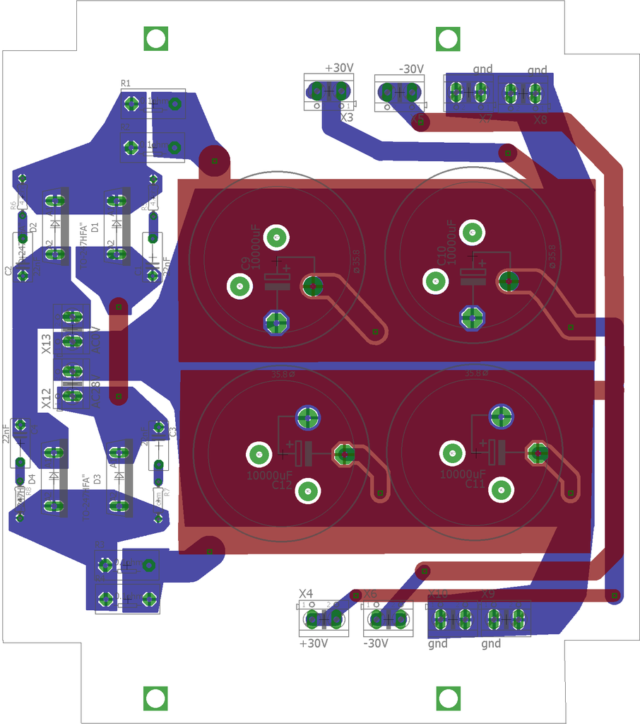
PSU board:
The output grounds including the GLB should be connected to the last two caps.
The ground and power traces should run parallel.
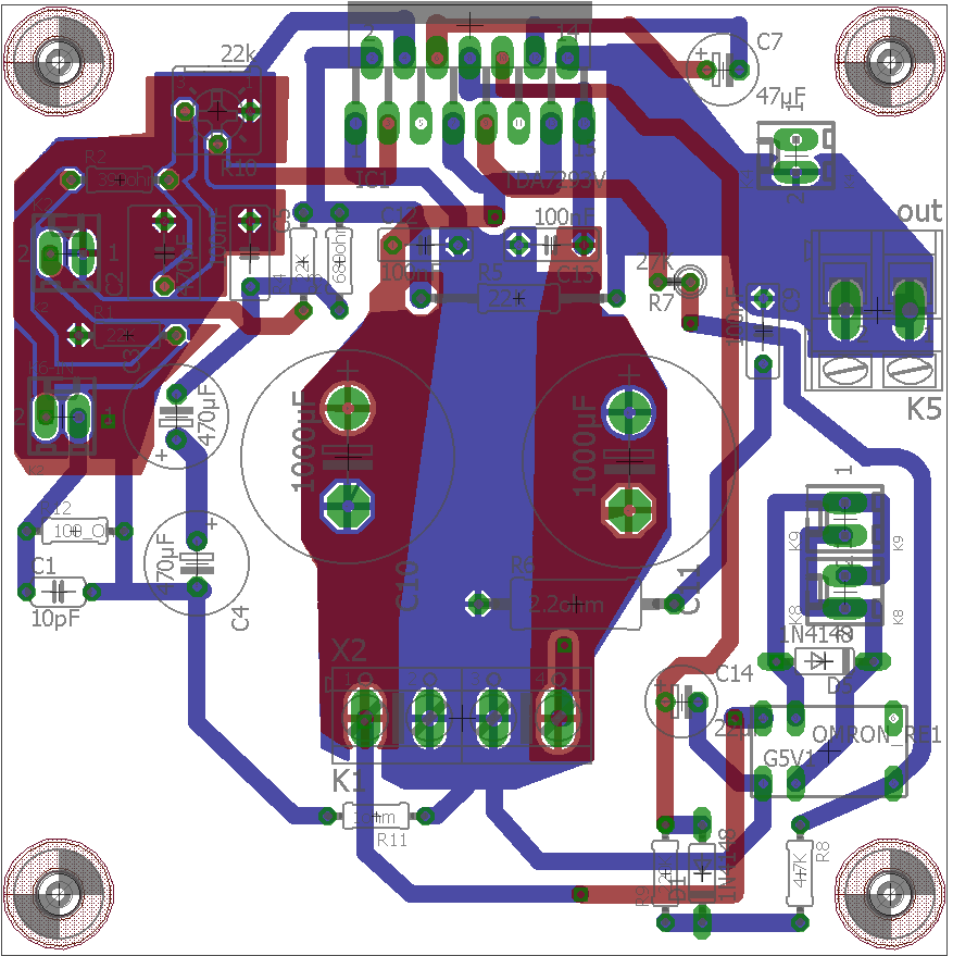
Amp board:
The input section should be redesigned. Loops are too big and the high impedance traces are too long and not shielded.
Crossover board:
You have seen how sensitive the low level signals are. This layout is going to pick up interference.
The output grounds including the GLB should be connected to the last two caps.
The ground and power traces should run parallel.
Amp board:
The input section should be redesigned. Loops are too big and the high impedance traces are too long and not shielded.
Crossover board:
You have seen how sensitive the low level signals are. This layout is going to pick up interference.
forgot, at the start of the crossover is a buffer amp, I put in 3 fold amplification. Just before the TDAs is a poti, because they have to be adjusted for each speaker anyway. And there are 2 RCs at the TDA boards, a low and a high pass.
crossover can take a while. Whats better, one ground plane and all the other things on top? Or 2 separated gounds. The suplly is some 14 pin chip, have to look at it again. It will have next to no ripple. And each opamp has 100nF in their supply rail. Will maybe the GLB should go to the transformer, not onto the board.
Use separate grounds. Input/feedback and power/output. Overlap the power traces with the ground plane. It helps if you draw the schematic with the layout in mind. You only need to make your layout look like the schematic.
Connect the power to the devices with the highest current first, these are usually the output devices.
Don't randomly connect parts to the ground planes. Follow the current flow from power caps, to bypass caps, to outputs and inputs.
Use correct decoupling/bypass layout. It is important that the caps have a low impedance connection to the op amps. Route the power to the cap, then to the device. Place the cap grounds of the two caps close together, this can also be used as the device's output ground.
I guess the xover board I will re organise ant try to put some rails in for the voltages
amp board is only 70 x70
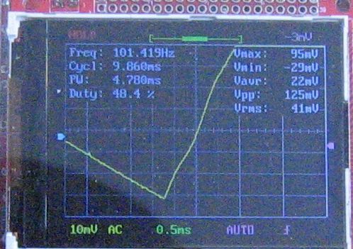
this is before the at the retifier before 0.1ohm resistors
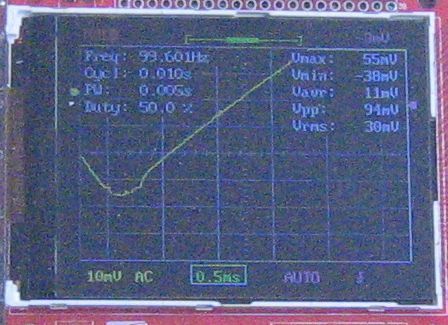
and this is after the resistors. No ring. Have to check,there must be a way to get the images out of the scope.
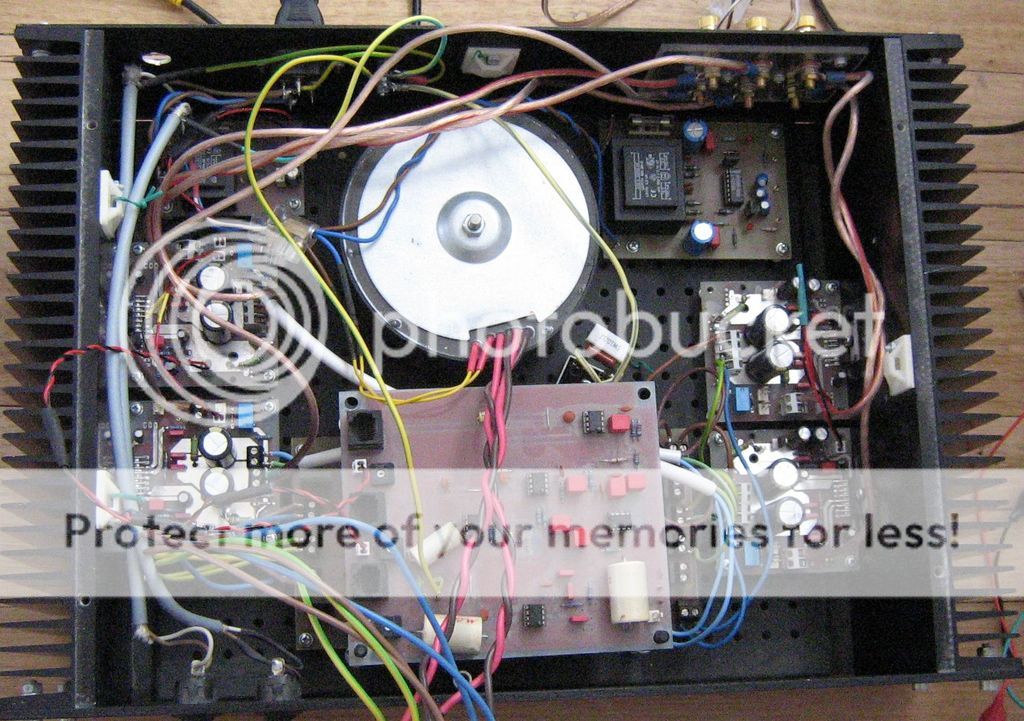
put the amp together, just for testing. If I turn the crossover the way as in the picture, there is no buzz. If I turn it the other way so the signal cable runs unter the toroid secontarys, there is hum. Shielded or not, so could use a short twisted cable. At the moment the xover has no power connection, just ground. So have to keep this in mind when doing the xover.
Last edited:
Small signal resistors with 27k input load, 22k feedback, is backwards; but, the easy solution is to change both to 25k.
TDA7293's amplifier board power caps, datasheet is misgiven, max is 470u upon the amplifier board power circuit. Bigger is more ringing and more heat and not useful--bigger goes on the power board, not the amp board.
Pinout is mad--put feedback resistor under board, directly to chip pins. It fits easily.
On typical layout with TDA7293, gain multipler is conveniently close to one rail's voltage, unfortunately with +-40vdc the divider ought to be 40x, which is not convenient for audio resolution, but there's good news to be had if your voltage isn't that high.
Exception: Had the bootstrap cap been hooked up just like a TDA7294, then those figures get worse (as in less stable at a given voltage). Might want to check the hookup.
I would like to see the power supply simplified by re-locating filters closer to the need/purpose locations. When filtering the transformer and rectifier, do it on the AC side of the rectifier. When filtering the DC to remove higher frequencies, do it at the edge of the amplifier board (preferably individualized per channel, handily blocking crosstalk). Specifically, capacitive filters on the power supply board must be either higher (example: 33nF) or lower (example: 22,000uF) than the audio band. SO, if you need capacitive filters, that cover only a portion of the audio band (example 1u~470u), move those to the amplifier board (the point where the DC umbilical cable joins the amplifier board, is a handy place for DC noise filters).
Filters work much better when positioned close to the need of them.
I do like the 10,000u||10,000u per each rail.
An embellishment that I would like to see added to the power supply board, is LED's, perhaps not more than 8ma apiece, individually, for each rail. Unlevel rails can break the TDA7293. The LED's won't beat measuring equipment, except that the LED's are always connected, which is a fair advantage.
P.S.
And then apologies: I did not spot your main problem. I think what could help spot the problem is pencil sketches of the circuits and hookups. Sure, nobody has spotted the problem yet, so, I'm suggesting to help us see it. I do like the sketches.
However, if this process is going too slowly or too much bother, and if the amp performs fine with battery powered source (like your phone), then you could probably, successfully, punt, with input transformers.
I was worried about the LEDs adding some noise, so I did not put them in. For some odd reason when switched off the current PSU board discharges a lot at the positive rail, its 1 V or so next morning, the negative is -10V or so.
Its +-28V,
Am thinking of using 680/22k to set the gain, instead 680/27k.
Ok, will replace the 1000uF with 470uF then
Its +-28V,
Am thinking of using 680/22k to set the gain, instead 680/27k.
Ok, will replace the 1000uF with 470uF then
DC is a non-switching application, and then no signal is no noise. Instead, they'll pull double-current (or maybe only 1/3rd more) in the presence of noise, and eat up a little noise. The 8ma per rail is not enough drag to degrade the performance of the power supply. But, serving as indicators, they still could save you from a shock.I was worried about the LEDs adding some noise, so I did not put them in.
In the application suggested, noise is not likely to be a consideration at all, due to the low current. However, had there been a noise, it will get consume in the LED and its resistor and not arrive at the output tap of your power board. As none of this is likely, due to low current, I can't suggest this as an audio improvement that everyone should do. However, I can suggest that an 8ma LED per each rail, at the power board, is seriously unlikely to harm the audio quality. I claim that they're quite useful as safety devices.
The number of times that I have put in a safety that didn't increase the audio quality is on record. Like Bon Ami, hasn't scratched yet.
All of my safeties are audio effects of minuscule effectiveness that isn't newsworthy, but they do actually also work as safeties. It is not going to hurt your audio. The amplitude for audio effectiveness is minuscule and probably is on the favorable side (with real music signal, an actual amp, and a real speaker).
P.S.
There would be a reciprocity failure if this was carried to an extreme--I did say 1 led (with series resistor), per each rail at no more than 8ma per rail. A huge amount more is beyond the relevant scope, so claims of it being helpful are not up-scalable at all.
Well the 470u is a maximum. 330u~270u per rail is closer to ideal. And I personally like 220u||220u (per each rail, at the amp board). Any and all of those figures is a huge improvement because they're figures that we can work with.Ok, will replace the 1000uF with 470uF then
The costs of using 220u||220u (per each rail) at the amp board, is a slightly more difficult install; and, the benefits are halved resistance and halved inductance, so that almost all caps work as perfectly as audiophile caps, or better.
The costs of using single 470u (per each rail) is that the response of the cap affects the response of the audio, with the caveat that the small variances have gain applied--same proportion as the amplifier's gain; so, you'd require rather favorable quality of caps.
The thing is that I have a very few of near-ideal 470u caps, and they're discontinued. However, pairs of ordinary quality 220u, used tandem, will replace the audiophile 470u caps directly. The tandem 220u do take more space; but, achieve audiophile results in a way that is reproducible and produce-able, and suited for publication.
Just saying that it would be good if you didn't require the audiophile quality caps. Simple tandem/parallel pairs of ordinary caps can replace audiophile caps in most applications.
I don't know what your stock of on-hand materials are; but, I though that capacitor matter (and workaround) was worth a mention.
P.S.
There would be a reciprocity failure if this was carried to an extreme--I did say two parallel caps for power on the amp board, per each rail. A huge amount more is beyond the relevant scope, is likely to cripple layout effectiveness; so, claims of it being helpful are not up-scalable at all. Two per rail means two, not fifty. Surprisingly, it was necessary to say that.
overkill PSU
None of the embellishment with caps and RC's are big enough to harm audio.
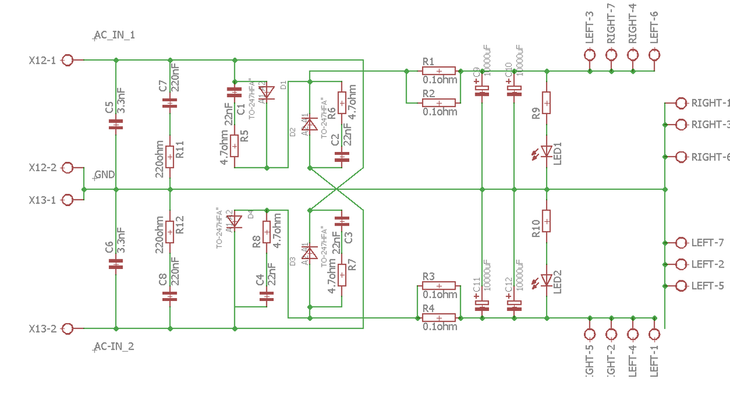
However, I would suggest to bypass R1, R2 with MBR1645, and bypass R3, R4 with MBR1645. That's because hindering the charge speed and recoup charge speed C9, C10, C11, C12 is absolutely certain to harm audio, because real audio signal. Do remember that you're powering woofers. In such case, any series resistors between the transformer and reservoir/tank capacitance functions mainly like using a far cheaper/smaller/thinner transformer, which would then run up cost for a bigger thicker heavier transformer, just so you could put resistors in the wrong place.
The low loss schottky diode bypasses that I have suggested will work; however, it is possibly more important to consider that R1, R2, R3, R4, are in the wrong location. Such filtering needs to come after C9, C10, C11, C12. Had the filters been better positioned, they'd be a lot more effective and ever so much easier in getting them to work effectively.
Other than that foobar with the resistors to decrease transformer effectiveness and decrease audio linearity, the other parts of the power supply look good. Its pretty far ahead, actually. But, do mind the positioning of the noise filters, because they probably shouldn't be on that board.
Last edited:
The 2u2 will affect audio signal at the speaker. Those caps are on the wrong board. It would be good if you'd didn't use that value anywhere in the amplifier power circuit.now that was fun

Exception, that value is possibly useful in the tweeter crossover, located in the speaker cabinet.
Thanks for your comments.
just about to order parts, so can still make changes. Then once the parts have arrived I double check the PCBs for part sizes and then order.
just about to order parts, so can still make changes. Then once the parts have arrived I double check the PCBs for part sizes and then order.

see how the current went up without the small resistors? Had to set it to 20V per unit now, 1mA=1mV

so half the current over double the time, this would be 1/4 the EMC at least, as its governed by I and di/dt.
This is good.
The DC filters that you have omitted from the amplifier board can now be added back at the edge of the amplifier boards. Do account for the DC cable (connects between the two boards) if you're doing intense analysis.
I hadn't meant to say that you had done any wrong filters previously. What I was on about is the placement. Power board at post#177 looks awesome, except that you need to short R7 and R8 (because those caps C1, C7, C2, C8 need charged at MAXIMUM SPEED per each and every bass beat of music). If you want more filters, I'm in favor of it, so long as you position the filters as close as possible to the need of them.
I posted with the assumption that this is a power amp; however, if this was a preamp or other very low current application, then my input was not relevant.
- Home
- Amplifiers
- Chip Amps
- how to get rid of interferences-TDA7293