You mean the big one is the magnetizing current, and the 2nd small one the PSU caps charging? Gues fair enough, its about 1:10 the transformer, so 500mA out would be 50mA in. Interestingly its way quiter, the toroid, than sitting on the timber floor. And first time I mounted it wires facing down, had more hum. Physical hum, not out of the speakers.
BNC Patch Leads High Quality RG59 for CCTV Cameras to DVR Video Cable | eBay
BNC patch lead 15 cm, for a lazy AUD 1.50 or so, this would be something worth considering? Its shielded all the way through.. Same in RCA costs more in really short lengths and I got the best results with a cut up antenna cable.
BNC patch lead 15 cm, for a lazy AUD 1.50 or so, this would be something worth considering? Its shielded all the way through.. Same in RCA costs more in really short lengths and I got the best results with a cut up antenna cable.

Have you actually put .01 uf or .1 uf ceramic caps across the outputs of all the transformers as they go into the rectifier? Getting rid of the RF components of the 50 hz is very important & very cheap. The vertical components of your waveforms, the nicely sloped ones are not nearly as prone to transmit to the gain stages.BNC patch lead 15 cm, for a lazy AUD 1.50 or so, this would be something worth considering? Its shielded all the way through..
Capacitor needs to be 1000 vdc rated old fashioned or 350 VAC or higher rated. I've salvaged some 375 VAC rated ,01 ceramic disk caps from an 90's tv, but distributors don't stock them that I have noticed.
Yes, per the article, snubbers with a resistor in series with the cap are slightly better. Fitting one component across the input of a bridge rectifier along with the fat transformer leads is hard enough for me, thank you. I'll leave soldering on two components without cooking one with the iron to you. Putting wires from the rectifier to a little board with the snubber on it just makes little antennas for the RF to transmit. At least the transformer leads you can twist so they cancel each other.
Last edited:
I just think that a smaller PSU board will make it possible to improve the positioning of the ground and power connections. If you are looking for inspiration, a good place to start is http://www.diyaudio.com/forums/vendors-bazaar/276145-ringnot-power-supply-chip-amps-bare-pcbs-assembled-tested-units.html#post4366692. The builder's guide is full of good info.
Last edited:
the Eagle has landed already, will post the layout tonight. What I did, put 2 power connections each side, because there will be 2 TDAs each side. Should that be a new thread?
So power in straight from toroid, short lead. Then 2 short power leads right and left to the TDAs.
So power in straight from toroid, short lead. Then 2 short power leads right and left to the TDAs.
Extremely wrong. 1000 uFs have self inductance from being wound and do not short out RF well. Impedance of inductance increases proportional to the frequency, which means wound capacitors don't do the job on sharp edges. 0.1 uf ceramics have almost no self inductance and are installed to give any sharp edges of the current waveform a slope, cutting the ability to couple to gain stages. If you can afford 1 uf ceramics of the proper voltage rating, go ahead. But .01 uf has been the traditional value.I guess so, don't really need the small caps as there are 1000uFs on the amp boards as well
Also after the rectifier, the shut off of the diode of about 0.6 v produces another sharp edge that needs another ceramic cap to give it slope.
ages ago I found something, small capacitors parallel to the big ones would help at high frequencies, they would discharge faster
power supply - What's the purpose of two capacitors in parallel? - Electrical Engineering Stack Exchange
pretty much coose it abitrary
power supply - What's the purpose of two capacitors in parallel? - Electrical Engineering Stack Exchange
pretty much coose it abitrary
Capacitors at the far end of long leads can never meet a fast changing demand for current.
If the load requires a fast changing current capability, then the long leads MUST BE ELIMINATED.
This is achieved by locating the local supply rail decoupling at the load. The ultra short capacitor leads between the cap and the load inherently have low inductance and allow a fast change in current demand. It is another case of small loop areas for the current circuit.
ages ago I found something, small capacitors parallel to the big ones would help at high frequencies, they would discharge faster
power supply - What's the purpose of two capacitors in parallel? - Electrical Engineering Stack Exchange
pretty much coose it abitrary
That is before and after a voltage regulator. A regulator needs to be able to pull HF current that can only be supplied by a small cap. Same as the TDA amp that also needs a small cap near the power pins.
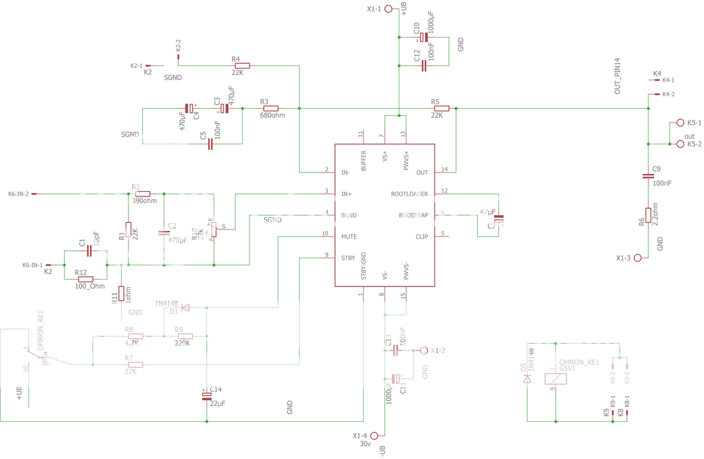
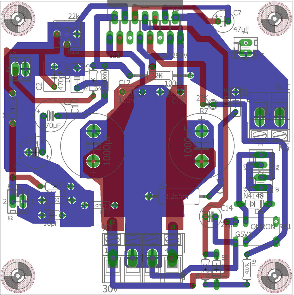
The board in post 152 has the AC rectifier a coupla centimeters from a very fast 20 v/usec op amp. Although the sharp edge transients are suppressed right there with a 0.1 uf ceramic cap, there are long leads coming over from the transformer carrying them and putting the 500 khz to 1 mhz components out in the air.
Successful commercial amps I own don't do that. They put the rectifier next to the transformer over at one end of the box with the filter caps including the ceramic, and the Peavey ones have a steel bulkhead around the transformer. They put the high gain parts at the other end of the box. They connect PS to gain with twisted pair carrying DC with 500 khz to 1 mhz already filtered out.
Meanwhile the Mark Whitney proposed filter board previous had no ceramic filter caps on it, just huge electrolytics.
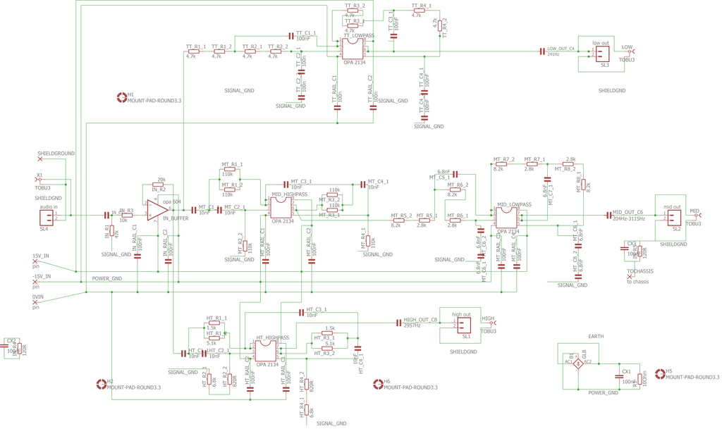
Further more, this board has 20 v/usec slew rate op amps (opa2134) with no 22 pf or 33 pf ceramic cap around the feedback resistor to keep the RF from being amplified. Didn't work when I tried 12 v/usec op amps, they oscillated .
Y'all carry on your conversation, I'm tuning out.
Successful commercial amps I own don't do that. They put the rectifier next to the transformer over at one end of the box with the filter caps including the ceramic, and the Peavey ones have a steel bulkhead around the transformer. They put the high gain parts at the other end of the box. They connect PS to gain with twisted pair carrying DC with 500 khz to 1 mhz already filtered out.
Meanwhile the Mark Whitney proposed filter board previous had no ceramic filter caps on it, just huge electrolytics.
Further more, this board has 20 v/usec slew rate op amps (opa2134) with no 22 pf or 33 pf ceramic cap around the feedback resistor to keep the RF from being amplified. Didn't work when I tried 12 v/usec op amps, they oscillated .
Y'all carry on your conversation, I'm tuning out.
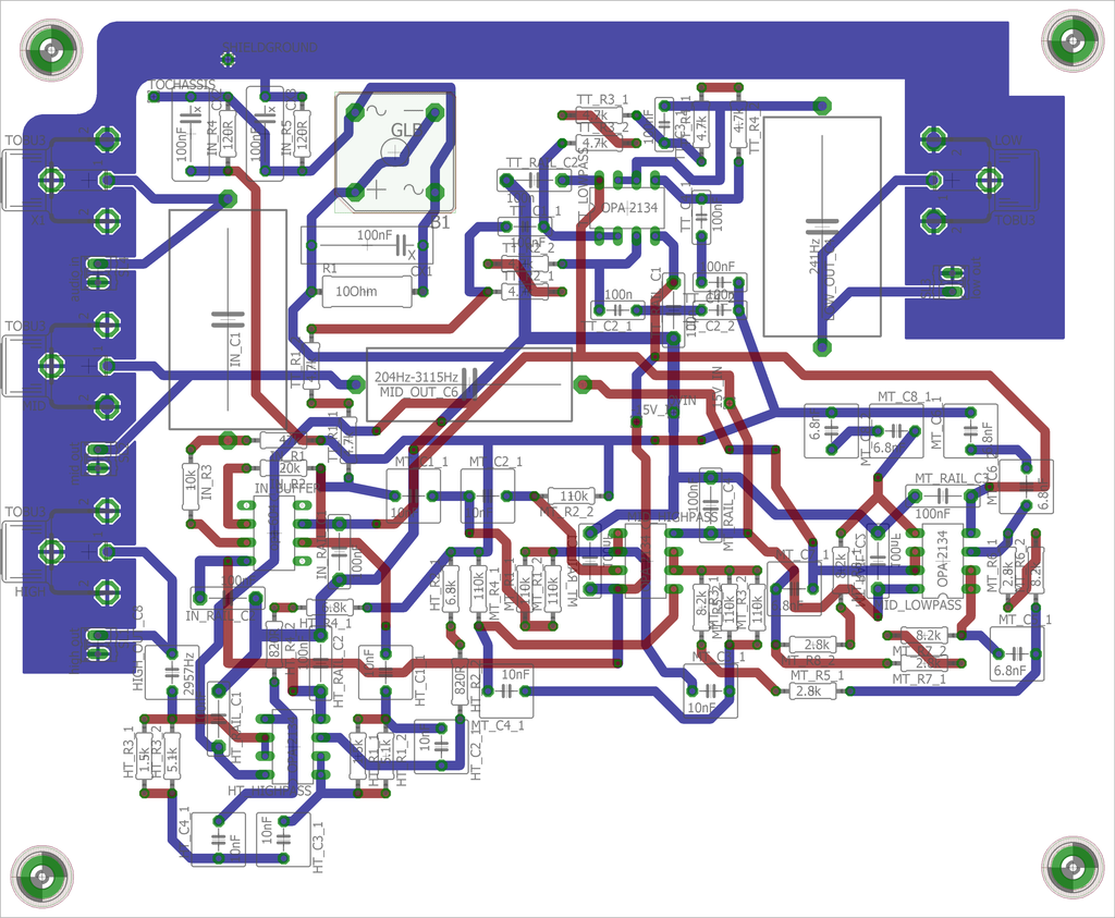
The AC rectifier on the crossover board is part of a ground loop breaker and only passes current in the case of a critical error.
The "Mark Whitney proposed filter board" is a Quick fix. By cutting up the old board we can see what HF content is present and if any extra's are needed. This PSU is only for the four amp boards. The Crossover board has its own transformer and PSU.
The "Mark Whitney proposed filter board" is a Quick fix. By cutting up the old board we can see what HF content is present and if any extra's are needed. This PSU is only for the four amp boards. The Crossover board has its own transformer and PSU.
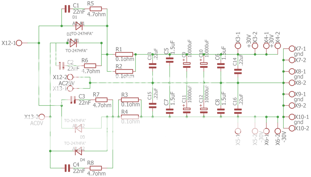
the existing PSU is on a 70um copper board with lots of planes, I won't be able to get the elcos out.I can remove the small ones, just cut the legs off. It has 100nF ceramics across the diodes.
Ceramice, because they have higher ESR, so you get a small resistor there too, so it makes a bit of a snubber. New board has 100nF and 100R parallel to each diode.
The diodes are ultra fast soft recovery HFA15
http://www.vishay.com/docs/94054/vs-hfa15tb6.pdf
and then before the capacitor banks there are 2 off 0,1ohm resistors.
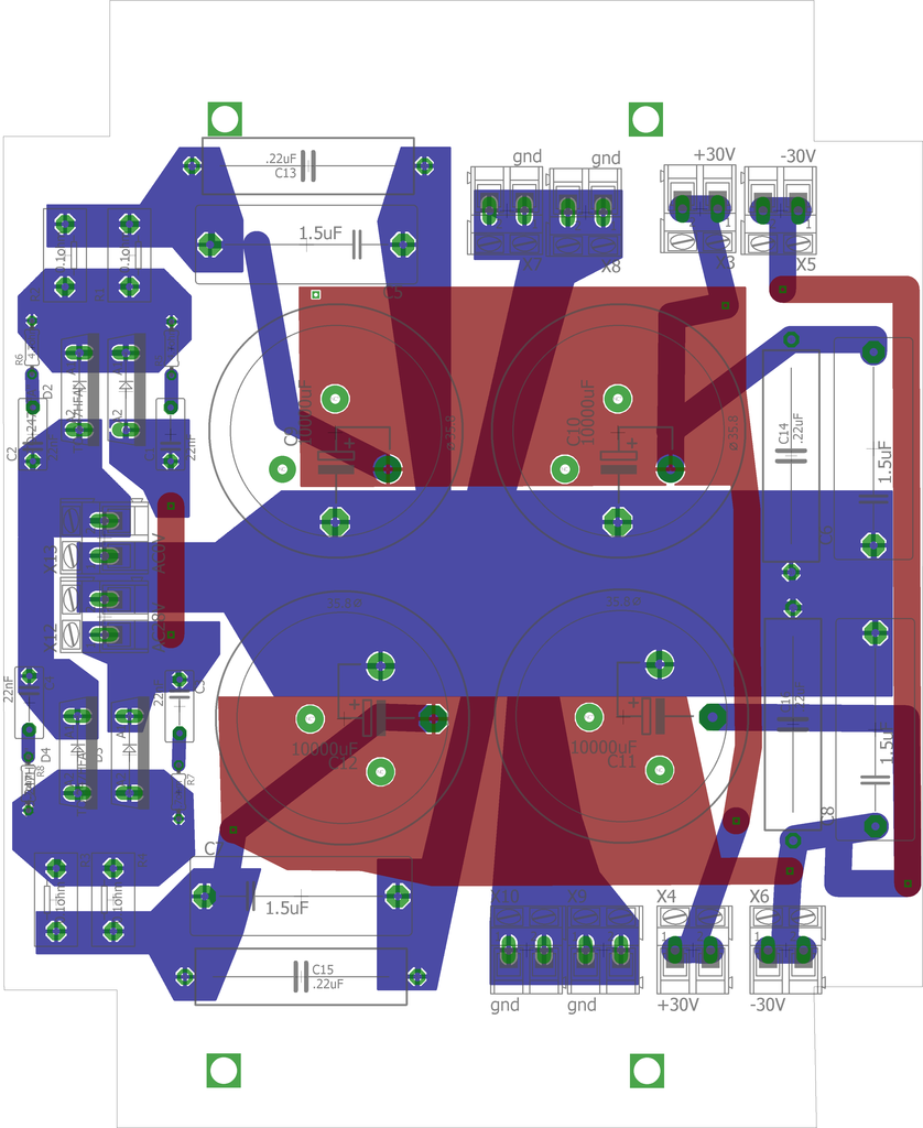
New board is next to the toroid, the cable goes in at about a few in long. Then it sends both voltages and gnd to both sides, so the cables to the amps are shorter. I will make a photo tonight with the printout of the PSU board. So its small caps can go, as there are 1000uF and then some 100nF or so at the TDA boards on the power rails. The linked PSU was for a class D amp, might have higher frequencies in power draw
Tapping for the GLB will be next to the 1st capacitor, where the messy currents are the highest. There is a little needle/pin connector
Ceramice, because they have higher ESR, so you get a small resistor there too, so it makes a bit of a snubber. New board has 100nF and 100R parallel to each diode.
The diodes are ultra fast soft recovery HFA15
http://www.vishay.com/docs/94054/vs-hfa15tb6.pdf
and then before the capacitor banks there are 2 off 0,1ohm resistors.
New board is next to the toroid, the cable goes in at about a few in long. Then it sends both voltages and gnd to both sides, so the cables to the amps are shorter. I will make a photo tonight with the printout of the PSU board. So its small caps can go, as there are 1000uF and then some 100nF or so at the TDA boards on the power rails. The linked PSU was for a class D amp, might have higher frequencies in power draw
Tapping for the GLB will be next to the 1st capacitor, where the messy currents are the highest. There is a little needle/pin connector
Last edited:
- Status
- This old topic is closed. If you want to reopen this topic, contact a moderator using the "Report Post" button.
- Home
- Amplifiers
- Chip Amps
- how to get rid of interferences-TDA7293