Mark W's diag Post37 is perfect.
that's not your mistake !Not perfect enough or the TDAs would not have gone up in smoke.
If he can be bothered to fit a low wattage bulb into his Mains Bulb Tester and use it to power on any and every modified mains powered project, then he deserves all he gets.
maybe it was static shock, when I undid some connections of the power supply. Should have completely discharged the capacitors.There are some situations where a small voltage spike in the TDA input destroys something and next time they are powered up, they blow up.
While I am rebuilding the amps, found this on grounding:
Grounding and Shielding Audio Devices
http://www.calex.com/pdf/4ground_shield.pdf
same as Marks post.
While I am rebuilding the amps, found this on grounding:
Grounding and Shielding Audio Devices
http://www.calex.com/pdf/4ground_shield.pdf
same as Marks post.
Your just wasting your time randomly trying things. My idea was to first get one channel to work without hum and then add a second. Fix any hum problems before adding a third channel. We may need to modify the amp PCB or change the ground layout.
We will only know by taking small steps and knowing what we have bone to make things better or worse.
We will only know by taking small steps and knowing what we have bone to make things better or worse.
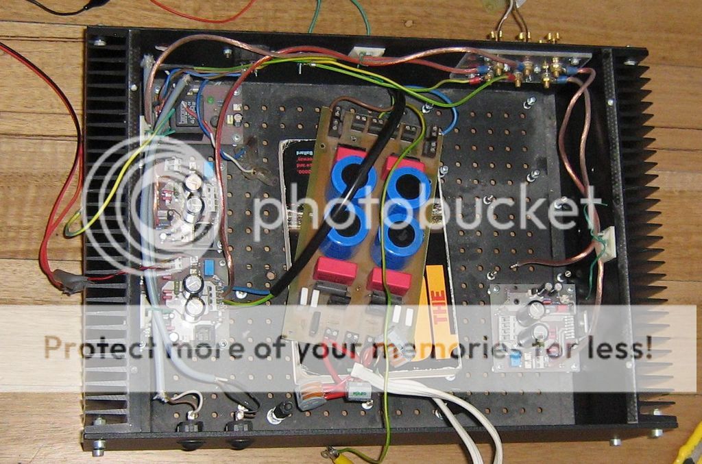
(1). It could be important that the ground (0V) leads connecting the four amps to the PSU are as short as possible and have approximately the same length. The best way to accomplishing this is by placing the PSU between the four amp boards.
(2). Very important to run the power ground (0V) leads close to the + and - leads. As in twisting the three together.
(2). Very important to run the power ground (0V) leads close to the + and - leads. As in twisting the three together.
Thats why I thought I make one star point for the power ground next to the board, and from there go back to another point, where eventually all the grounds meet. Have to make a shorter PSU board otherwise the toroid has to go into a separate box.For now that board is that long, because it has a few extra small caps for high frequencies

That's the ripple on the supply rail when you draw some current from the PSU.
Turn the horiz down to show two cycles so that you can see a whole waveform.
I misunderstood what that little plip at the top of the waveform meant. It was explained to me a year or so back, but I've already forgotten the explanation. I need to do more homework/review.
Turn the horiz down to show two cycles so that you can see a whole waveform.
I misunderstood what that little plip at the top of the waveform meant. It was explained to me a year or so back, but I've already forgotten the explanation. I need to do more homework/review.
Have you tested your wiring by powering via a Mains Bulb Tester?Transformer sounded a bit angry.
The waveform is symmetrical, so thats all good. With no load there is no ripple. I just zoomed in to show the blip. Could be when the diodes are switching/recovering. ebayed an amp meter clamp. 2V ripple is quite a lot, at 20W already. Did not want to leave it running for too long to get a better picture, its only 5W resistors, should have been 10W, so they get hot fast. Otherwise maybe there is a chance to zoom in on that blip. Maybe that snubber thopi, parallel to diode an100nF with 100ohm in series.
Dont have a mains bulb tester, would have to cook up one. But from memory, the TDAs dont like to be zapped on the input. Its MOSFETs. I measuresd with the multimeter, that all connections are ok. If the inlet side of the TDA is gone, it will blow up next time on power. The 1000uF capacitors were still charged to 20V between - and 10, but only about 1V between 0 and + on the symmetrical on the amp monoblocks. I will check all the connections tonight and then power it on.
Dont have a mains bulb tester, would have to cook up one. But from memory, the TDAs dont like to be zapped on the input. Its MOSFETs. I measuresd with the multimeter, that all connections are ok. If the inlet side of the TDA is gone, it will blow up next time on power. The 1000uF capacitors were still charged to 20V between - and 10, but only about 1V between 0 and + on the symmetrical on the amp monoblocks. I will check all the connections tonight and then power it on.
They sell light bulb sockets at the hardware store. Case can be an old room heater, an old toaster, any old appliance. Room heaters you can see through the grill if the light is on. Even an old fan. Most of the above will have a fused plug or a fuse inside on the circuit board, which can be hacked (cut the land) to delete everything else.
I think I told you in post 2 about the .01 uf disk cap on output of the rectifier. You can put a 1000 v rated one on the input of the rectifier too, the output of the transformer, the way dynaco did.
Really, all that 50 hz stuff needs to be behind a steel wall if it stays in the main chassis with the amp inputs. Sharp voltage edges emit RF at 50 hz.
https://e2e.ti.com/support/power_ma...-measuring-and-reducing-output-voltage-ripple
something reg ripple, but does not explain the blip. Maybe the HF bit. Its for switch mode supplies though
Gauss meter gets a high reading on the wires on the transformer, but then it disappears further along the cable. I guess shortening the transformer leads and rejigging the PSU board can help. But first still have to find the reason.
The angry transformer, its just plain 50Hz hum, no overtones. Its just lying on the timber floor and some rubber washers underneath. Humming away, can hear it from 1m, just so. The funny thing, the side where the wires come out is more magnetic than the back. May have to encapsulate it. But at present its some distance from anything else and the Gauss reading drops quite fast, within a few inch ist from 200 to 0. PSU has no Gauss reading. So lets see tonight, what happens/ 10AM over here.
Last edited:
This Use a twist (and other popular wires) to reduce EMI/RFI | EE Times and this http://www.updatemydynaco.com/documents/GroundingProblemsRev1p4.pdf may be more helpful in finding solutions to this hum problem.
More. http://support.sbg-systems.com/customer/en/portal/articles/1408684-magnetic-fields-and-disturbances
More. http://support.sbg-systems.com/customer/en/portal/articles/1408684-magnetic-fields-and-disturbances
Last edited:
off to the builders market to get the bits. Incandescent bulbs are phased out, See what they got, there may still be one in the shed. Twisting the DC wires, ok, there is 1V AC on top of 30V DC. But I reckon a decent current. Tough question, as the current drives the magnetic field, not the voltage. As long as it pulsates should be same as bad? I.e. out of the toroid is the same current as behind the PSU. More or less, as there is none at the 0V crossing.
The current though the transformer is 7 to 10 times higher than the DC current though the load from the PSU. Current only flows when the rectified AC voltage exceeds the DC voltage of the PSU. The upward line on your oscilloscope display shows the voltage increasing as the transformer is supplying current to the capacitors and load. The downward line shows when the capacitors are supplying current to the load.
http://www.radio-electronics.com/info/circuits/diode-rectifier/rectifier-filtering-smoothing-capacitor-circuits.php
http://www.radio-electronics.com/info/circuits/diode-rectifier/rectifier-filtering-smoothing-capacitor-circuits.php
Last edited:
- Status
- This old topic is closed. If you want to reopen this topic, contact a moderator using the "Report Post" button.
- Home
- Amplifiers
- Chip Amps
- how to get rid of interferences-TDA7293