Just read your other post - it is not clear whether you are doing bandpass filtering with opamps before the power amps, or whether you are trying to do the bandpass filtering as part of the poweramp's feedback loop. If you are doing the latter - don't do that.
If you are doing the former, make sure all of the signal grounds only connect to the power ground at ONE point, and isolate the two with a 10 ohm resistor bypassed by a 100nF capacitor. Make sure you are using proper star earthing techniques too.
the grounds meet at every monoblock as well.
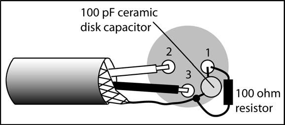
something like this (from Church Sound: Church Sound: Preventing Hum And Radio Frequency Interference (RFI) In A System - Pro Sound Web)
measured, when the amps are running (mute off), the Gauss meter gets about 2uT for the housing. Lab power supply is at 8 and so is the toroid. When the amps are not running (mute on) then there is no reading for the housing. Now I got the ferrites, put them around the power cables does not help either.
Last edited:
Is your case aluminum? All the humless amps I own have a steel case. If so a shim stock lining might help. found in old plastic PC tower cases, cuttable with shears. Also sold in rolls at industrial supplies and some auto supplies. I recommend .006".
Do you have a .01 uf uf ceramic cap across the output of the power rectifier? diodes make switching noise at double power line frequency.
You can twist your input pair of wires with a hand crank drill and a vise, or in extremis, a pair of pliers. You do run an analog return direct from the RCA or 1/4 phone jack direct to the board, don't you? If running three board from one jack, try one. You may need an audio buffer IC near the jack to run to three boards spread the signal around at low impedance.
Last edited:
top and bottom of thecase is steel, sides are alu cooling fins, front ans back are alu as well.
The signal is split into 3 via an active / opamp crossover. But that is not connected, to eliminate as source of the noise. It really comesdown to that short audio cable from the crossover to the monoblock.
The signal is split into 3 via an active / opamp crossover. But that is not connected, to eliminate as source of the noise. It really comesdown to that short audio cable from the crossover to the monoblock.
Well short the output of the crossover to see if the hum is being picked up by the crossover coil or the wire to the amp boards. If gone, it is not the wires particularly.
If the crossover has coils, they can be big hum antennas. When driven by a low impedance source (op amp), less so maybe.
All my amps are full frequency, so I have no experience with passive crossovers before the power amp. I have used an active line level graphic equalizer before the amp with usual RCA cables in and out: worked fine. And the tone controls in my preamp (PAS2) don't cause hum or hiss.
I got the hum out of my op amp disco mixer with double pi filter on power coming in, RCLRCR, plus a steel case. L was a 20 turn toroid salvaged out of a switcher supply, one on hot and minus, and that was on DC lines from a DC wall transformer. Plus I had a steel case. I don't think you've done any of the above yet. Plus you might have an appliance nearby causing some magnetic fields. Hammond organs used to hum if an AC driven clock was set on top on the left side. They had a wood case. Aluminum stops electric fields, but not magnetic. You'll notice PC cases have sheet steel liners behind the plastic, not aluminum foil which would be a lot cheaper to cut up.
Last edited:
http://i212.photobucket.com/albums/cc4/Steffen595/jumperlead_zpsai1ocfex.jpg
its aleready everything removed. The 2 transformers at the bottom of the image are not connected.The xover top center is not connected either. Just that cable from left to right connecs 2 amps. The 2 white cables feed 2x22V from the toroid into the power supply.
its aleready everything removed. The 2 transformers at the bottom of the image are not connected.The xover top center is not connected either. Just that cable from left to right connecs 2 amps. The 2 white cables feed 2x22V from the toroid into the power supply.
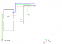
no idea why this happened. Just blew up 3 TDAs. Turned the supply by 90 deg and re connected it. If I turn it 90 deg, the transformer will not fit. Unsoldering the TDAs is a bit of a pain, no idea, if the PCB boards will survive.
Got the other amp still to test some cable ideas.
It might be easier and cheaper in the long run to get these audio switch mode supplies and digital crossovers. Fried about 10 TDAs so far. As much fun as it is to route new PCB designs, its time and money consuming as well. Time I don't have, there is still some home renovation to be done plus enrolled in a remote course.
Mark W's diag Post37 is perfect.Try this: Rotate the power supply board so that the board is in the middle top of the chassis.
It is important to twist the parallel leads.
It shows the dedicated mains safety PE connected direct to Chassis, via a short wire
It shows the close coupled triplet supplying power.
It shows the close coupled speaker pair.
It shows the Safety connection from Main Audio ground to Chassis, via a short wire.
And he tells everyone to twist the leads. So that is a twisted triplet for power and twisted speaker pair. Do not plait triplets and quads. Twist !
Last edited:
- Status
- This old topic is closed. If you want to reopen this topic, contact a moderator using the "Report Post" button.
- Home
- Amplifiers
- Chip Amps
- how to get rid of interferences-TDA7293