Might I ask why you don't have a metal nibbler?
How thick of metal can a nibbler deal with? I have a small one, but my case is made of 1/8 inch aluminum. Can the nibbler be used on material this thick?
Russellc
That would have to be a pretty big nibbler. the small hand versions ussually only go up to abou 0.063" (1/16).
Have you guy's read this thread?
http://www.diyaudio.com/forums/pass-labs/178780-drilling-tapping-conrad-heatsinks.html

Have you guy's read this thread?
http://www.diyaudio.com/forums/pass-labs/178780-drilling-tapping-conrad-heatsinks.html
Last edited:
My 2 cents
Dremell and loads of atachments I can't live witout.
Dremmel and cutting disk best way to cut PCB on a budget.
Old pedal from sowing machine variable speed.
Best thing about it makes much less noise than normal power tools.
I will try to post same pictures tomorow.
Dremell and loads of atachments I can't live witout.
Dremmel and cutting disk best way to cut PCB on a budget.
Old pedal from sowing machine variable speed.
Best thing about it makes much less noise than normal power tools.
I will try to post same pictures tomorow.
I apologize for causing this to turn into how to cut real panel for a power entry module.
In other news, it looks like you got the drilling and tapping done fairly well, hopefully you don't have too much more to do aside from soldering.
In other news, it looks like you got the drilling and tapping done fairly well, hopefully you don't have too much more to do aside from soldering.
Ok, back to building an amp... 🙂
I have all I need in place to build the amplifier circuit and mount it to it's heatsink.
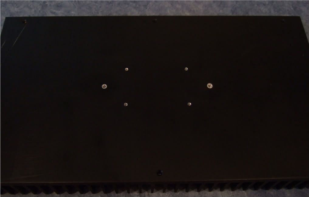
Here is the heatsink, with the holes sanded smooth and cleaned with rubbing alcohol to remove the last oil and sandings/shavings.
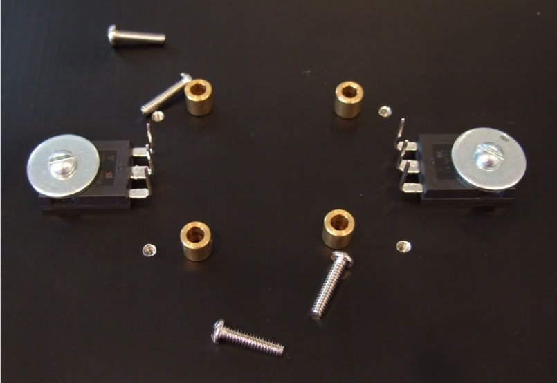
Here is the hardware, 6-32 bolts and fender washers on the transistors, brass spacers and 4-40 bolts on the board
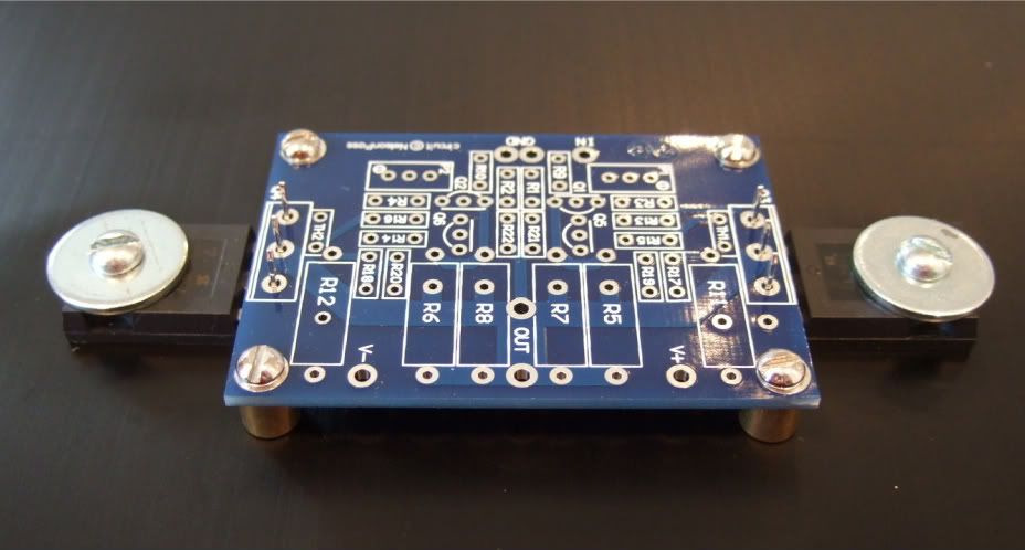
A dry run to check fit
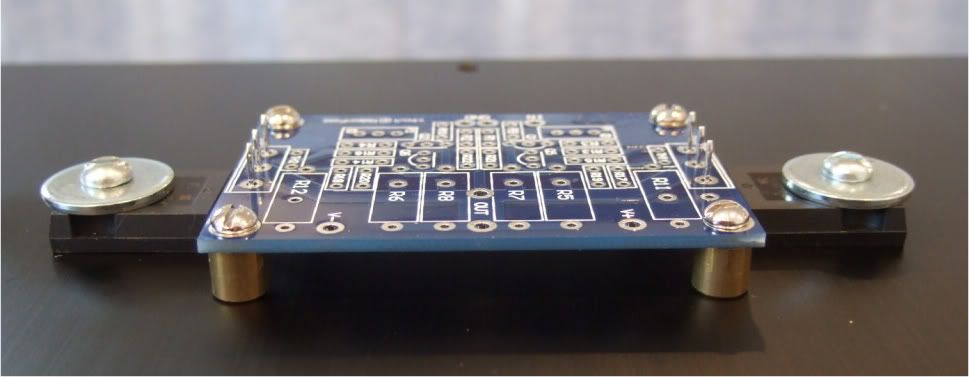
Spacing looks good! Now to complete the board...

Stuffing the board. Have your meter at the ready and measure everything before soldering!!! It will save headaches later!!

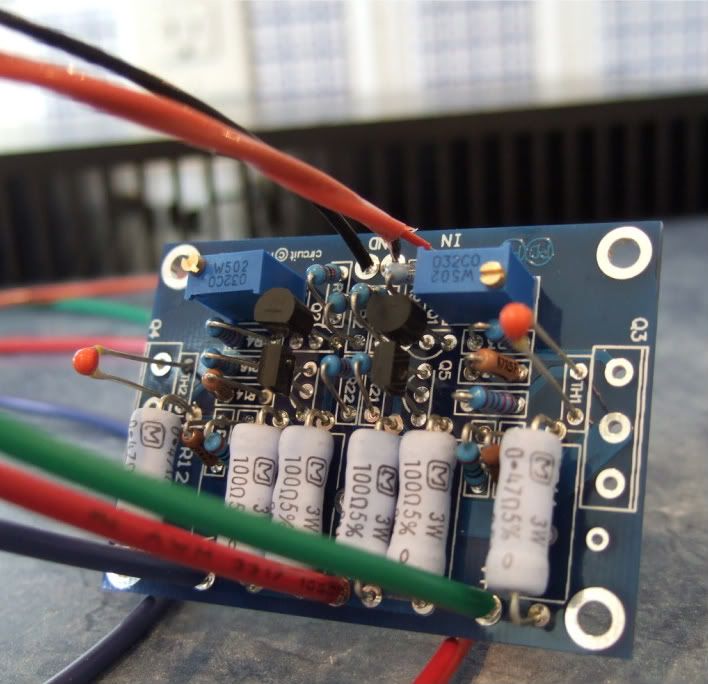
OK, the board is stuffed and the wires attached. My color coding is as follows;
Black - ground
Blue (V-)
Green (V+)
Red (+) out
Red/black twisted pair in orange jacket is input + and -
I like to have the wires much longer than needed to help facilitate neat and tidy wiring later.
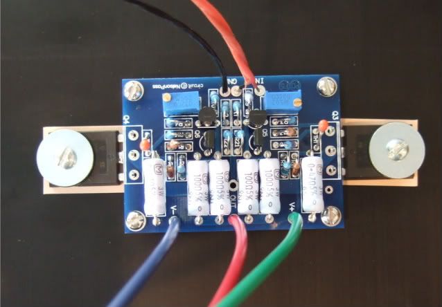
On the heatsink with silpads attached.
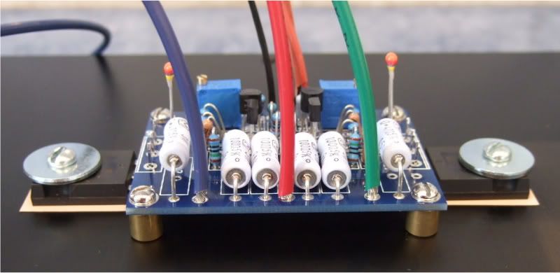
In this photo you can see the following -
The thermistors are not bent down yet, as I need to get some loctite for the threads before I am actually done... Same with the transistors, they are not soldered and trimmed.
The two 3W resistors on the outside of the PCB (R11 and R12) are standing up off the board so that when it becomes time to set bias, I can easily connect leads across the resistors.
I have all I need in place to build the amplifier circuit and mount it to it's heatsink.
Here is the heatsink, with the holes sanded smooth and cleaned with rubbing alcohol to remove the last oil and sandings/shavings.
Here is the hardware, 6-32 bolts and fender washers on the transistors, brass spacers and 4-40 bolts on the board
A dry run to check fit
Spacing looks good! Now to complete the board...
Stuffing the board. Have your meter at the ready and measure everything before soldering!!! It will save headaches later!!
OK, the board is stuffed and the wires attached. My color coding is as follows;
Black - ground
Blue (V-)
Green (V+)
Red (+) out
Red/black twisted pair in orange jacket is input + and -
I like to have the wires much longer than needed to help facilitate neat and tidy wiring later.
On the heatsink with silpads attached.
In this photo you can see the following -
The thermistors are not bent down yet, as I need to get some loctite for the threads before I am actually done... Same with the transistors, they are not soldered and trimmed.
The two 3W resistors on the outside of the PCB (R11 and R12) are standing up off the board so that when it becomes time to set bias, I can easily connect leads across the resistors.
Last edited:
It's a common practice to mount Rs such as your 3Ws, that might get quite hot, spaced off the board somewhat to allow for good air flow around the component and help keep heat off the board.
6l6,
why have you put these fantastically detailed, but uncropped pics on photobucket?
Do you realise how much that slows down a DIYaudio page download?
why have you put these fantastically detailed, but uncropped pics on photobucket?
Do you realise how much that slows down a DIYaudio page download?
Remote hosting the pics saves the bandwidth costs to the DIYaudio server.
I could also go and resize them in photobucket... I guess I haven't noticed, as my pages load quickly and auto-resize to a smaller photo that you can click into.
But as a photo is worth 1000 words, some members might want the detail...
I could also go and resize them in photobucket... I guess I haven't noticed, as my pages load quickly and auto-resize to a smaller photo that you can click into.
But as a photo is worth 1000 words, some members might want the detail...
My solution to avoid rectangular cutting.
Neutrik - powerCON 20 Amp
Pretty much the same openings as XLR. The only problem is that they should not be "hot" plugged or unplugged.
Neutrik - powerCON 20 Amp
Pretty much the same openings as XLR. The only problem is that they should not be "hot" plugged or unplugged.
My solution to avoid rectangular cutting.
Neutrik - powerCON 20 Amp
Pretty much the same openings as XLR. The only problem is that they should not be "hot" plugged or unplugged.
I like the Neutrik 32 amp powercon.
6L6...... There's probably "mixed schools of thought" about this (as there seems to be with many F5 build comments......) but when you build your NEXT F5, you might want to mount the PCB a little lower on the heatsink. Theory is, that with convection cooling, most of the heat generated by the output transistors will rise (that part is fact.....), and therefore a good hunk of the heatsink BELOW the transitor will not be that hot and therefore not contribute equally to the cooling (that's the hypothesis accompanying the theory). I mounted my PCBs about 1/2" below the heatsink centerline, to compensate for the cooling flow. (Touch testing tends to confirm the results--upper part of the heatsink, under load, is cooler than the lower portion. QED.)
As for making "square holes", etc, I'm lucky--and have access to a CAD/CAM milling machine..... having said that, I also have used a Roto-tool with a cut-off disk to do chassis work before, and it works quite well. (And yeah, I also have a bunch of toolmaker's rat-tail metal files, that help to dress out milling bit radii, etc, etc.
Love your thread--goes to show there is more than one way, to generate the first watt of Class A. I'll get some pics of mine to you.....
Ken
6L6...... There's probably "mixed schools of thought" about this (as there seems to be with many F5 build comments......) but when you build your NEXT F5, you might want to mount the PCB a little lower on the heatsink.
I thought of that as well! But 2 things stopped me... first, see section 14 of this document -- ESP - Heatsink design and transistor mounting
Second, it is extremely important (for me, anyway..) to have the boards, and on them the potentiometers in a place where you can get a tool to it easily. If the boards were really low it would be harder to adjust the trimpots.
I would love to see your amp!
loctite ? are you serious ? if you insist on using it , use the blue otherwise you'll be using a torch to get anything undone .
loctite ? are you serious ? if you insist on using it , use the blue otherwise you'll be using a torch to get anything undone .
The problem is that the threads are actually covered in what is effectively anti-seze... Powered aluminum and a bit of petroleum... And although I have cleaned out the holes and the threads of the bolts, I actually do want to use a bit of a threadlocker.
Remember, there is going to be an awful lot of expansion and contraction cycles on this, and the interface is a dissimilar metal. (Steel bolts on aluminum) So the is a distinct possibility that they will walk one way or another.
Blue Loctite, applied with the very tip of a toothpick, about one nano-liter per hole. 🙂
- Home
- Amplifiers
- Pass Labs
- How to build the F5