why don't you start your own thread ?
nothing wrong having same thing covered by more than one member 😉
nothing wrong having same thing covered by more than one member 😉
6L6, How would you feel if I were to also document my F5 build on your thread.
I would have no problem with that at all!
However, I think that Zen Mod has a good point with starting another thread...
Your build will be different enough from mine that somebody new to all this might want to have things separated to make easier to understand.
The original F5 thread has become unmanageable. There is lots of good information there, but finding it is tedious.
I don't have the specific knowledge (or electronics background, as I'm a Pilot...) to make a Wiki on the F5. So this is going to be my contribution to the effort.
Why when clicking to this thread does my browser get stuck @
downloading "mystatus.skype."
Why should a slow reply from skype hold up display of the thread page?
Now it's "googlesydication.com" that is holding up the display of the thread page.
downloading "mystatus.skype."
Why should a slow reply from skype hold up display of the thread page?
Now it's "googlesydication.com" that is holding up the display of the thread page.
O.K.! O.K.! I'll start my own thread...
yeah ....... you're not welcome here ....


yeah ....... you're not welcome here ....
No! flg, please don't take that for anything but the (very bad) humor that it is supposed to be... You are more than welcome to use this thread if you desire!
No, I will move on. Yet another F5 thread. You are welcome to puruse the new thread. I will basically focus on driving ridiculous current to low impeadance loads... And cooking sausage... on a Hibatchi... Along with trying to allow some to feel more like a member, that can search, read, and then ask a question. I am not holyer, smarter, or better, at anything, except maybe cooking sausage, than anyone else. but, as a public forum, we expect people to try a littler harder than asking any question off the top of their head and expect an answer from an expert, right now. As far as the F5 goes, there is tons of info in the 2 big threads already. But, I know, it'll take 2 weeks to read it all!!! Get started if your new 😀
yeah ....... you're not welcome here ....
boyz , pardonne moi if that was over the line ;
that certainly wasn't my intention
i'd like to think that anyone that's been following this forum would know that zen mod was just fooling around and being his wiseguy self . not to mention the emoticons he used in that post.
personally i think two separate threads would be best since the reason for this one was to focus on building the basic f5 for newbies and yours flg is not . i'll be following both . 🙂
cheers Woody
personally i think two separate threads would be best since the reason for this one was to focus on building the basic f5 for newbies and yours flg is not . i'll be following both . 🙂
cheers Woody


i'll be following both . 🙂
cheers Woody
you and me both! As i am getting ready to build one myself!
Ok, today I got some drilling done. A lot of effort with not much to look at...
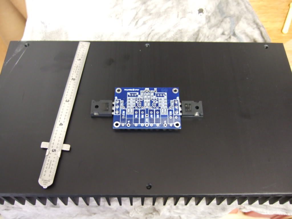
This is the amp board and the 2 power transistors. They will be mounted to the middle of the heatsink.
Once the holes are measured and marked, I made some starter holes with a set punch. The 4 in the middle will be 4-40, the two on the outside 6-32
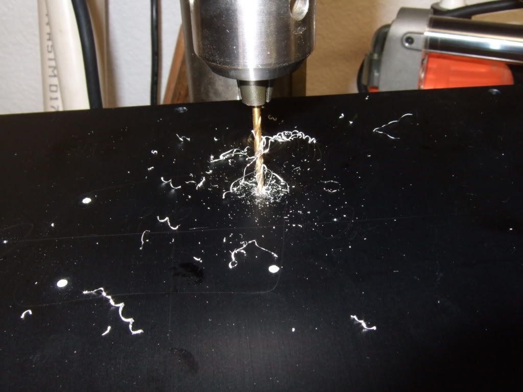
Drilling
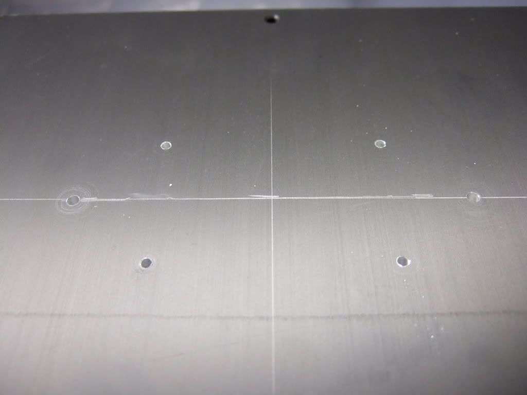
Drilling complete
My friend was kind enough to tap the holes.
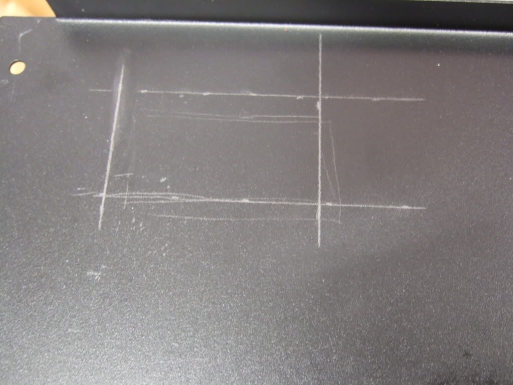
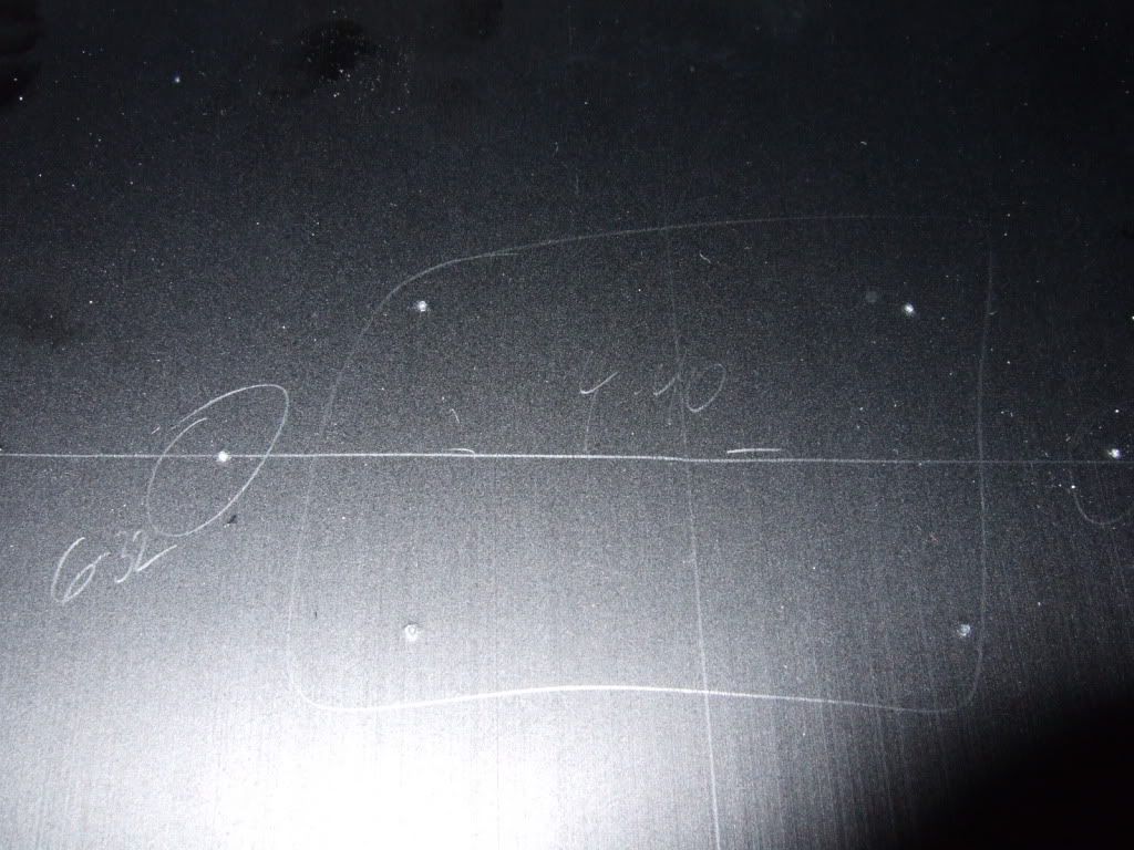
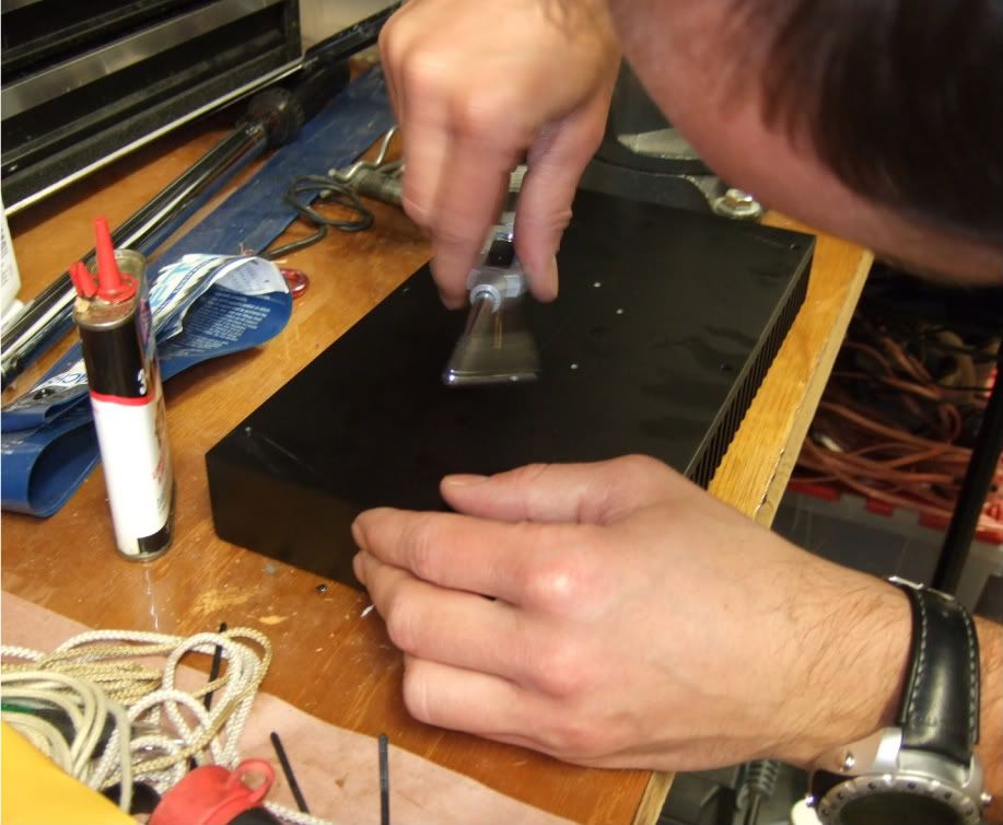
Marking the opening for the inlet module, slightly undersized. You will see why in the next photo.
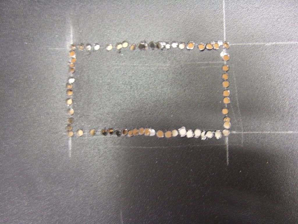
Many holes later, ready to be knocked out and filed smooth
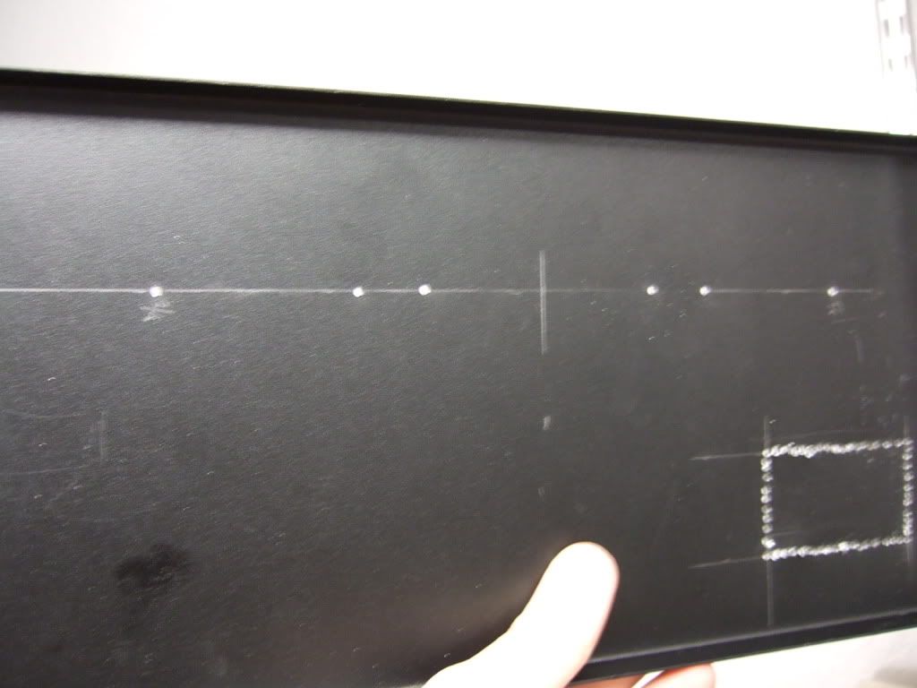
Pilot holes for the speaker posts and RCA jacks
This is the amp board and the 2 power transistors. They will be mounted to the middle of the heatsink.
Once the holes are measured and marked, I made some starter holes with a set punch. The 4 in the middle will be 4-40, the two on the outside 6-32
Drilling
Drilling complete
My friend was kind enough to tap the holes.
Marking the opening for the inlet module, slightly undersized. You will see why in the next photo.
Many holes later, ready to be knocked out and filed smooth
Pilot holes for the speaker posts and RCA jacks
Might I ask why you don't have a metal nibbler?
I can file flat.
(Although, by the looks of it, I can't drill very straight... 😀)
It looks like you drilled at least 60 holes just for that power entry module. I am asking because it seems like it would have been much easier to just use a nibbler instead.
- Home
- Amplifiers
- Pass Labs
- How to build the F5