I'm assuming this is a Fender reissue of the 1959 Bassman? Knowing which version of the amp you have is important because over the years Fender changed the schematic for the Bassman well over a dozen times, and their reissues usually don't use the original schematics. The 5F6 is considered the "classic" Bassman; it was introduced in 1959. I'm guessing the schematic for the "59 Ltd is similar to the 5F6 but not exactly the same.
Here's a link to a thorough explanation of what is involved with biasing the power tubes of an amp.
How to Bias a Tube Amp
And here's a link that does the maths for you.
Tube Bias Calculator
Here's a link to a thorough explanation of what is involved with biasing the power tubes of an amp.
How to Bias a Tube Amp
And here's a link that does the maths for you.
Tube Bias Calculator
Last edited:
A quick internet search yielded this thread on biasing the 59 LTD: https://ampgarage.com/forum/viewtopic.php?t=20145
If you're not sure how to measure plate voltage (as your initial post suggests), I think you should have someone more knowledgeable and experienced bias your amp. The plate voltage in a Bassman can get as high as 450 volts. A slip of a finger and you could shock yourself badly, potentially lethally, or cause a spark that takes out components.
If you're not sure how to measure plate voltage (as your initial post suggests), I think you should have someone more knowledgeable and experienced bias your amp. The plate voltage in a Bassman can get as high as 450 volts. A slip of a finger and you could shock yourself badly, potentially lethally, or cause a spark that takes out components.

I'm not familiar with your particular amp, so I can't offer more specific advice. A schematic or bias adjustment instructions in the owner's manual would be useful.
Perhaps this will help: I'm guessing that there is a bias pot on the bottom of the chassis with a notch on its shaft for a flat blade screwdriver. Adjust the shaft in one direction and the bias setting will go up and adjust it in the other direction the bias setting will go down. There is no one single setting everyone should shoot for, however; as long as you don't set the bias too high and make the plates on the output tubes glow reddish orange, you're fine. The filaments in a tube will glow reddish orange and that's nothing to be concerned about, but if the plates themselves glow, that's bad and you will destroy those tubes quickly unless you adjust the bias lower.
So what you could do is to turn the bias pot slowly in both directions: the direction that makes the amp have more gain is the direction you need to make sure doesn't result in "red plating." Turning the pot in the other direction poses no threat to the tubes. In fact, the more you turn the adjustment in that direction, the longer the power tubes will last. As long as the output tubes' plates are not glowing red/orange, adjust the bias pot to where the amp sounds best to you.
But if there is no adjustable bias pot on the bottom of the chassis, you need to take the amp to a tech or someone who knows what they're doing.
Instead of poking around with a multimeter under the hood. A breakout jig like this would be better: But even this kit should be using shrouded banana plugs instead of these exposed ones. If I owned a biasing jig I would cut off exposed banana plugs and replace them with shrouded ones.

Shrouded banana plugs:

Shrouded banana plugs:
This instagram post covers measuring and adjusting the bias on a different line of Fender amps from your Bassman. However, read through it. There's a video where he connects an alligator clip to the test point (might not be in the same place on your amp) just so you can see how to do it. Clip onto the test point BEFORE you turn on the amp, that way your hands won't be anywhere near the circuit when it's energized.
Please, PLEASE remember that this is High Voltage and we don't want you to die. Work safely. Always keep one hand in your pocket when measuring a live amplifier, don't provide a path for electricity to travel through your body.
Uncle Doug video on safely measuring a cathode resistor.
Oh, and I've broken 2 tubes with one of those bias testers mentioned above, they put pressure on the pins and break the glass. I'd stay away from the Noval bias tester. Octal tubes don't have pins passing thru the glass like that, they're prob ok.
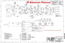
I believe you'd adjust the bias in this design by changing R46 or R47 (voltage divider in the negative voltage supply) to change the amount of negative voltage allowed to flow to the grids.
Some fenders with this design (early Blues Jr, maybe?) come from the factory with an incorrect bias setting (too hot) and an adjustment to R46 is necessary to improve the sound and get a proper lifespan from the power tubes.
So ya, it's worth checking factory specs vs the tube datasheet.
Some fenders with this design (early Blues Jr, maybe?) come from the factory with an incorrect bias setting (too hot) and an adjustment to R46 is necessary to improve the sound and get a proper lifespan from the power tubes.
So ya, it's worth checking factory specs vs the tube datasheet.
I'm not sure that's the right schematic. Apparently Fender has made both a '59 Bassman reissue and a '59 Bassman LTD. i suspect the LTD is closer to the original 5F6 schematic. Of course it might be a moot point, since the 5F6 Bassman didn't have adjustable bias anyway. As far as i know, none of the classic Fender amps (1940s-1960s) did.On the schematic I found, there is no provision for adjusting the bias.
You can only check the bias voltage at the test point. Should be -52VDC.
Be extremely careful. One slip could damage the amp, or injure you.
If there is no bias pot, do nothing.
The way I've always biased Fender amps with push-pull output stage (i.e., 2 output tubes) and a bias pot:
1. Apply a sine wave signal (600 to 1000 Hz) to the input. Connect an oscilloscope (not a sound card input) to the speaker output with the speakers (or a power soak) connected..
2. Adjust the bias so crossover distortion (it looks like this: https://www.electronics-tutorials.ws/amplifier/amp_7.html) begins to be visible on the scope. Then adjust the bias till the crossover distortion just barely vanishes plus very slightly more.
- Done -
Last edited:
If so, you're in luck. If there are also two jacks for test probes then you can plug your multimeter into those jacks, , set your multimeter to measure volts DC, adjust the bias pot (slowly!) and dial in –52v. But if the amp sounds better to you with lower bias (the range between –52v and –25v or so), you can leave it there. A bias setting higher than –52v (–60 for example) will shorten the life of the output tubes.There’s round plastic circle with a slit in it for a screwdriver which I believe is to turn or down the bias.
It's illuminating to hear how adjusting the output tubes' bias changes the sound of an amp. Higher bias results in more gain and more "crunch." Lower bias results in less gain and a cleaner, more sparkly sound.
- Home
- Amplifiers
- Tubes / Valves
- How to bias a Fender Bassman 59 Ltd guitar amp?