Hello everyone. I am going to build a small guitar amp using a circuit based on the TDA8541 chip. This is only my second try at building an amp. My first one I used the TDA7052a and it turned out really great. I decided to build another one but then found out the tda7052a chip is discontinued and I can't find anymore. So I decided to try this TDA8541 because it looks really simple enough for me to build and seems to be available at most places I checked.
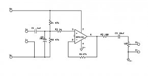
Can someone look at this circuit I attached and tell me how I could add in a volume pot or if it's even possible?


Can someone look at this circuit I attached and tell me how I could add in a volume pot or if it's even possible?
Attachments
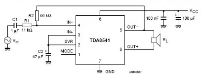
The input impedance (R1, 11k) is too low for an electric guitar, anyway, and the overall gain might be a bit low – possibly not. It might be worth doing an input buffer. In which case, volume control would be no problem. No, nothing sophisticated, a single FET would do fine, or an op amp, if you're building on vector board.
Alternatively, you could increase R1 to 47k (the lowest I'm willing to countenance for guitar, and even then it'll be blues/jazz), and replace R2 with a high value potentiometer- perhaps a meg, and if the amp's compensated to zero gain (wich detail I couldn't find, but the lack of a minimum gain suggests it is) you could use the circuit board as suggested.
Alternatively, you could increase R1 to 47k (the lowest I'm willing to countenance for guitar, and even then it'll be blues/jazz), and replace R2 with a high value potentiometer- perhaps a meg, and if the amp's compensated to zero gain (wich detail I couldn't find, but the lack of a minimum gain suggests it is) you could use the circuit board as suggested.
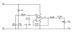
Add an extra capacitor to the output of your buffer, and put the pot from there to ground, wiper to the capacitor to the power amp chip.
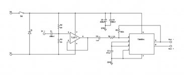
I hope I am doing an extremely scruffy sketch of the changes I would suggest – I assume the - volts on the 071 are not an extra power rail but the same as the ground on the amp? I've slightly complicated centre rail generation, and added a feedback resistor to your buffer. This changes nothing as it is now, but, should you need more gain, means that you can pur a resistor from the negative input to the centre rail.
I hope I am doing an extremely scruffy sketch of the changes I would suggest – I assume the - volts on the 071 are not an extra power rail but the same as the ground on the amp? I've slightly complicated centre rail generation, and added a feedback resistor to your buffer. This changes nothing as it is now, but, should you need more gain, means that you can pur a resistor from the negative input to the centre rail.
Attachments
Hello, sorry I didn't get back sooner. I got busy at work and didn't have any time until today to read your suggestions.
I have been reading about opamps and I think I made myself more confused. I am not sure about the grounds.
I have tried to implement your suggestion. Can you look at this schematic and tell me if I have it correct and if I have the grounding the right way?
I have been reading about opamps and I think I made myself more confused. I am not sure about the grounds.
I have tried to implement your suggestion. Can you look at this schematic and tell me if I have it correct and if I have the grounding the right way?
Attachments
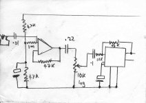
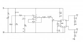
If you have a true ±9 volt supply then you don't need R1/R2 to centre your output; you put one resistor to true ground. But that complicates your power supply, since the TD8541 is single rail (actually, it generates its own centre rail on pins 2 and 3, and you could use this as a ground reference, at least fot the volume pot.) As you've biased the 071, any noise on the +ve rail is fed straight into the output, increasing hum and buzz and introducing the risk of motorboating, where a power transient pulls down the power supply, which feeds into the preamp creating a power transient, setting up a pop-pop-pop low frequency oscillation. Not nice. So I put a decoupled centre rail (two equal resistors and an electrolytic (at least 16 volts, value depends on the resistors you use for the divider chain- say 25µF. You've got 10µF? Fine, we'll use that.
If we need gain from the buffer amp (not certain) we now attach the gain resistor between this centre rail and the negative input to the amp. Or we put in another capacitor to ground to the end of the gain resistor. W could even put a tone control – but we won't.
I've done another of my scruffy sketches apologies, when I've finished moving I will get CAD software running on my laptop, somehow.
So, was I speaking chinese, there? I'm afraid that in my head it's clear, but explaining it isn't my strongest suit.
Attachments
Hehe, yes it's a little bit Chinese to me but I think I'm learning. I appreciate your help very much.
I decided not to use that TDA8541 because it's to small for me to solder so I switched to the TDA2822m because it comes in 8 pin dip.
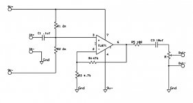
I attached a schematic for the buffer you described. Hope I got it right.")
I decided not to use that TDA8541 because it's to small for me to solder so I switched to the TDA2822m because it comes in 8 pin dip.
I attached a schematic for the buffer you described. Hope I got it right.
Attachments
Nope, there you've shorted out the input. C1 needs to go to the other end of R3. Otherwise, DC conditions seem right (as long as you've got an input capacitor on your - just a minute, the TDA2822m? but that's a stereo amp, not a bridge, so it's going to give a quarter the power unless I work out a way to polarity invert the signal. And it's maximum recommended voltage is only 9V, so that's down to a quarter again! (fortunately the 071 will run quite cheerfully off ±4.5V). Not that I don't understand; I just repaired a circuit board with surface mount components and my eyesight isn't up to it any more. But isn't there a DIL pack for the TDA8541? I feel sure I saw one.
The TDA2822m has a bridge mode. I was going to use the circuit they provide in the data sheet.
I'm afraid I don't understand where R3 gets connected. I can't make out where you have it in your drawings. It looks like it's connected from the + input to the middle of R1 and R2 the way you drew it.
I'm afraid I don't understand where R3 gets connected. I can't make out where you have it in your drawings. It looks like it's connected from the + input to the middle of R1 and R2 the way you drew it.
That's it. We might put a series resistor or diode in the + volt line and a capacitor to ground to prevent power supply problems between power and pre amp stages, but that's the essential. Is C3 really a paper 10µF capacitor as drawn? That might be excessively big. I definitely think a .22µF would suffice, but if you want an electrolytic for frequency response into the nether depths (and what loudspeaker are you going to use for that, pray?) remember the positive end is toward the amp.
One more. =/+s are tough little beasts, but they're not tubes. I'd suggest a series resistor with the input (go on, I never marked it. I was doing theoretical for you) so its internal protection can cut in if the input signal is something seriously nasty. Perhaps 10k or so; won't affect the performance measurably. Oh, go on, put a diode from the input to each rail (biassed off, obviously) while you're there, to prevent the input from trying to go outside them; you might get struck by lightning.
(Kindly excuse me if I'm not always serious.)
? That might be excessively big. I definitely think a .22µF would suffice, but if you want an electrolytic for frequency response into the nether depths (and what loudspeaker are you going to use for that, pray?) remember the positive end is toward the amp.One more. =/+s are tough little beasts, but they're not tubes. I'd suggest a series resistor with the input (go on, I never marked it. I was doing theoretical for you) so its internal protection can cut in if the input signal is something seriously nasty. Perhaps 10k or so; won't affect the performance measurably. Oh, go on, put a diode from the input to each rail (biassed off, obviously) while you're there, to prevent the input from trying to go outside them; you might get struck by lightning.
(Kindly excuse me if I'm not always serious.)
Your awesome Chrispenycate. I couldn't have figured any of this out without your help.
I'll add the changes when I get home from work tonight and maybe I can breadboard it and test it out.
I wish I could let you hear it when it's finished. I think it's going to be really good.
I'll add the changes when I get home from work tonight and maybe I can breadboard it and test it out.
I wish I could let you hear it when it's finished. I think it's going to be really good.
Hi there,
For a non-inverting amp like this, you will need to just add a resistance from Pin 2 ( Inverting input ) going towards 0 volt (Signal ground). But because you are single supply normally you add an electrolytic in series below it, then to ''ground''. Suggest 10 K and 1uF electro. Cap Polarity is positive toward top. 1 uF gives pretty much no rolloff of low frequencies on guitar. 10 K will give some gain. You can play around with ratio of resistance in feedback loop if you want more/less gain, but that will give plenty if going to a volume pot after this stage. Lower capacitance will give LF rolloff at higher frequencies. Look up non inverting op amp and you can see the gain formula.
For a non-inverting amp like this, you will need to just add a resistance from Pin 2 ( Inverting input ) going towards 0 volt (Signal ground). But because you are single supply normally you add an electrolytic in series below it, then to ''ground''. Suggest 10 K and 1uF electro. Cap Polarity is positive toward top. 1 uF gives pretty much no rolloff of low frequencies on guitar. 10 K will give some gain. You can play around with ratio of resistance in feedback loop if you want more/less gain, but that will give plenty if going to a volume pot after this stage. Lower capacitance will give LF rolloff at higher frequencies. Look up non inverting op amp and you can see the gain formula.
What voltages have you got on different pins? Pin 6, output, should be at the same as pins 2 & 3 (which are more difficult to measure because of the meter pulling current) half the way up the supply rail, equal to the junction of R1 and R2.
The first one should work; I was only trying to prevent power supply ripple feeding into the input with the resistor capacitor network; there should be no change in DC voltage.
The first one should work; I was only trying to prevent power supply ripple feeding into the input with the resistor capacitor network; there should be no change in DC voltage.
Hello guys, Thanks for helping me out with this.
I haven't had a chance to check the voltage on the pins yet. I'll hopefully get a chance tomorrow.
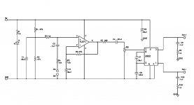
Here is some of what happens when I turn the circuit on. Either buffer circuit has the same results I found out. Without the buffer at all and just running the guitar signal straight into the amp part of the circuit it works pretty good but not the best tone. With the buffer included the tl071 chip won't work at all. It makes a pop..pop...pop sound. I switched it for an OPA134 that I had and then it works but only if I remove the 10uf input capacitor. I even tried exchanging for other tl071 chips and opamps but the OPA134 was the only one that would sort of work. I think I have the grounds wrong. I tied the signal ground together with the opamp and chip amp grounds and I'm not sure that is correct.
I added the complete circuit exactly how I made it so you can see if I connected something wrong. The audio chip is a TDA2822M in bridge mode.
I haven't had a chance to check the voltage on the pins yet. I'll hopefully get a chance tomorrow.
Here is some of what happens when I turn the circuit on. Either buffer circuit has the same results I found out. Without the buffer at all and just running the guitar signal straight into the amp part of the circuit it works pretty good but not the best tone. With the buffer included the tl071 chip won't work at all. It makes a pop..pop...pop sound. I switched it for an OPA134 that I had and then it works but only if I remove the 10uf input capacitor. I even tried exchanging for other tl071 chips and opamps but the OPA134 was the only one that would sort of work. I think I have the grounds wrong. I tied the signal ground together with the opamp and chip amp grounds and I'm not sure that is correct.
I added the complete circuit exactly how I made it so you can see if I connected something wrong. The audio chip is a TDA2822M in bridge mode.
Attachments
Last edited:
The TL071 worked when you had it as a buffer (output connect directly to inverting Pin 2 ).
In post # if you look at the 47K and 4.7K you have created a voltage divider with respect to ground. The non-inverting input sees a portion of the output voltage. To do this when you have a single ended supply (signal is biased to mid supply), instead of the bottom of 4.7K going to ground directly, just add a 1uF electrolytic in between that and your ground connection. For the ac signal appearing in feedback that is now its ground return point as it is decoupled from any DC offseting you would get tying direct to ground. Your circuit will work fine like that.
In post # if you look at the 47K and 4.7K you have created a voltage divider with respect to ground. The non-inverting input sees a portion of the output voltage. To do this when you have a single ended supply (signal is biased to mid supply), instead of the bottom of 4.7K going to ground directly, just add a 1uF electrolytic in between that and your ground connection. For the ac signal appearing in feedback that is now its ground return point as it is decoupled from any DC offseting you would get tying direct to ground. Your circuit will work fine like that.
The TL071 worked when you had it as a buffer (output connect directly to inverting Pin 2 ).
In post # if you look at the 47K and 4.7K you have created a voltage divider with respect to ground. The non-inverting input sees a portion of the output voltage. To do this when you have a single ended supply (signal is biased to mid supply), instead of the bottom of 4.7K going to ground directly, just add a 1uF electrolytic in between that and your ground connection. For the ac signal appearing in feedback that is now its ground return point as it is decoupled from any DC offseting you would get tying direct to ground. Your circuit will work fine like that.
I tried it like this and had the same results. Here is the schematic showing how I tried it.
Attachments
- Status
- This old topic is closed. If you want to reopen this topic, contact a moderator using the "Report Post" button.
- Home
- Live Sound
- Instruments and Amps
- How to add volume to TDA8541 circuit?